Flameless combustor with oscillating cavity fire stabilizing device

A technology of flameless combustion and oscillating cavity, which is applied in the direction of burners, gas fuel burners, combustion types, etc., can solve the problems of high catalyst cost, lower fuel self-ignition point, increased operating cost, etc., to improve stability and combustion safety performance, improve stability, and avoid flameout problems

Active Publication Date: 2019-10-18
HUAZHONG UNIV OF SCI & TECH +2
View PDF2 Cites 4 Cited by
  • Summary
  • Abstract
  • Description
  • Claims
  • Application Information

AI Technical Summary

Problems solved by technology

Based on the principle that catalysts can reduce fuel ignition concentration requirements, CN201710893746.3 proposes a catalytic flameless combustion device, which first uses a small flame to preheat, and then switches to flameless combustion by increasing the gas and air flow rates, but there are Due to problems such as unstable switching process and high catalyst cost, CA2240411C proposes a flameless burner, which sets a catalytic surface in the combustion chamber to reduce the self-ignition point of fuel, which is beneficial to the ignition of flameless combustion, but has complex structure and increased operating costs The problem
Based on the principle of flue gas mixing and preheating in the furnace, CN201610512122.8 proposes a heat exchange flameless combustion furnace and a flameless combustion control method, which promotes the backflow of flue gas through the gradually expanding furnace to promote the mixing in the furnace, but The problem of combustion stability when switching between the preheating phase and the flameless combustion phase is still not resolved

Method used


Image

  • Flameless combustor with oscillating cavity fire stabilizing device
  • Flameless combustor with oscillating cavity fire stabilizing device
  • Flameless combustor with oscillating cavity fire stabilizing device

Examples


Embodiment Construction

[0030] In order to make the object, technical solution and advantages of the present invention clearer, the present invention will be further described in detail below in conjunction with the accompanying drawings and embodiments. It should be understood that the specific embodiments described here are only used to explain the present invention, not to limit the present invention. In addition, the technical features involved in the various embodiments of the present invention described below can be combined with each other as long as they do not constitute a conflict with each other.

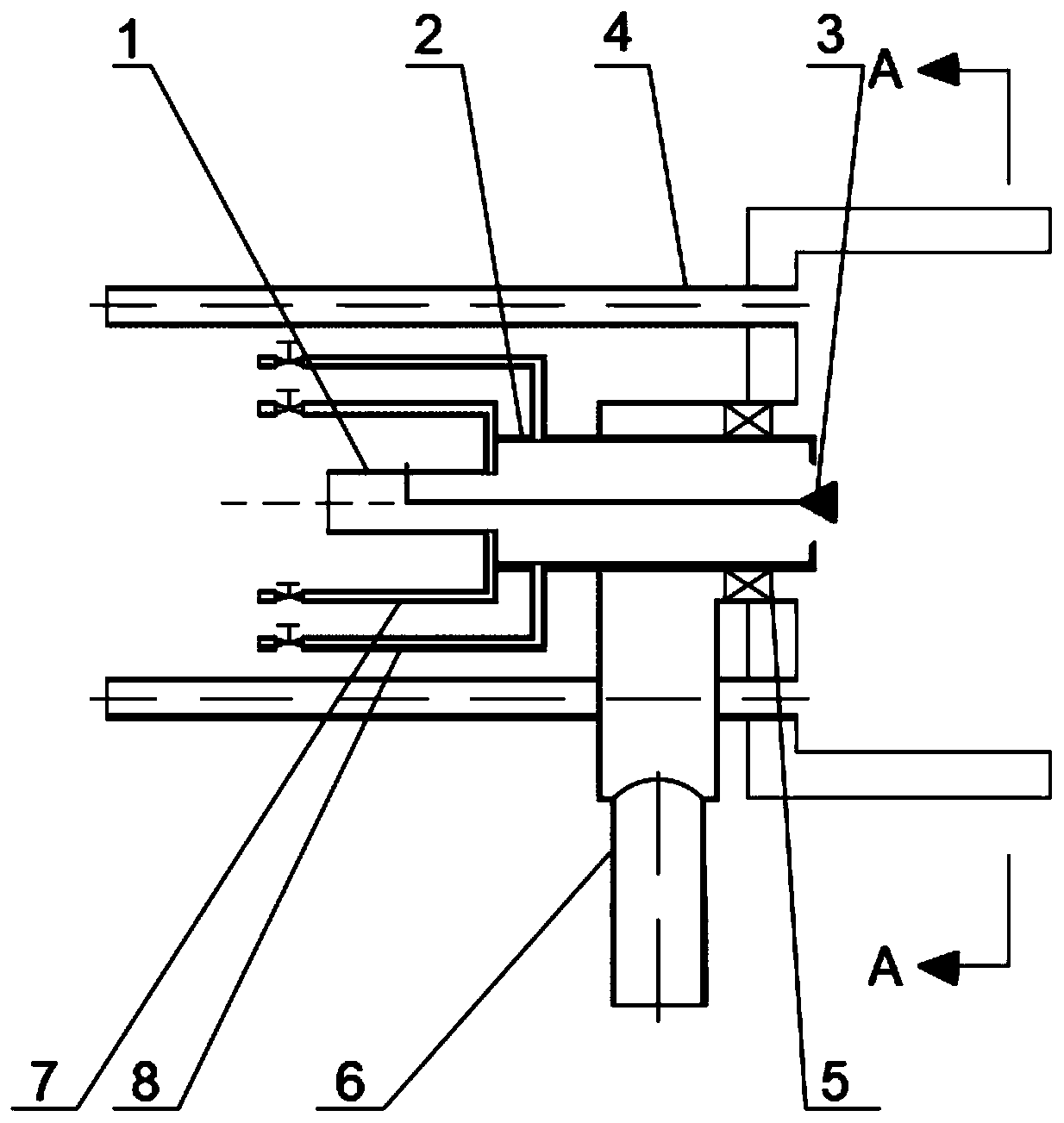
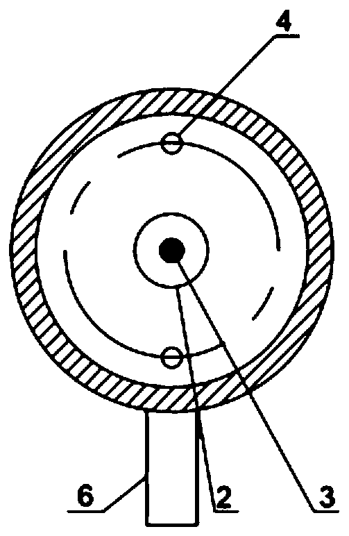
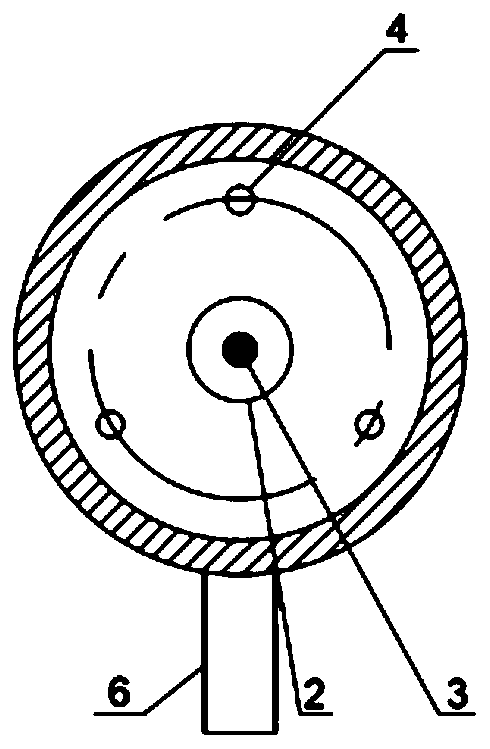
[0031] Such as figure 1 As shown, the preferred embodiment of the present invention proposes a flameless burner with an oscillating chamber fire stabilizing device, which includes a central gas nozzle 1, an oscillating chamber 2, an air conditioning nozzle 8, an air swirl Nozzle 6 and air direct injection nozzle 4, wherein:

[0032] The outlet of the central gas nozzle 1 is connected to the os...


PUM


Abstract

The invention belongs to the field of a combustor and particularly discloses a flameless combustor with an oscillating cavity fire stabilizing device. The outlet of a center fuel gas spray pipe of theflameless combustor is connected with an oscillating cavity and the center fuel gas spray pipe is used for providing fuel gas; air adjusting spray pipes are symmetrically arranged on the two sides ofthe oscillating cavity and are used for providing the air for the flue gas to be combusted in the oscillating cavity to form attended flame; the oscillating cavity excites the residual flue gas aftercombustion of the attended flame by the oscillating effect to form oscillating jet flow to be sprayed out; an air rotational flow spray pipe is embedded outside the oscillating cavity and is used forproviding rotational flow air at a preheating stage; and air direct spray pipes are symmetrically arranged on the outer side of the center fuel gas spray pipe in parallel and are used for providing the air for the flameless combustion stage. The oscillating cavity is provided and oscillating jet flow can be formed, so that uniform distribution of the flue gas in a hearth is guaranteed; furthermore, the attended flame can be formed in the oscillating cavity, so that the flameout problem when the preheating stage and the flameless combustion stage are switched is avoided.

Description

technical field [0001] The invention belongs to the field of burners, and more specifically relates to a flameless burner with an oscillating cavity fire stabilizing device. Background technique [0002] In recent years, frequent smog in many places in my country has endangered people's health. Therefore, air quality issues have received widespread attention. Among them, nitrogen oxides are one of the culprits of smog weather, so the reduction of nitrogen oxides is becoming the focus of the government's environmental protection work. The low-nitrogen combustion technologies currently used in the industry mainly include staged combustion technology, flue gas recirculation technology and premixed combustion technology. These technologies have limited emission reduction effects, cannot take into account high efficiency and cleanliness at the same time, and have problems with increasingly stringent environmental protection requirements. gap. The flameless combustion (Moderate&...

Claims


Application Information

Patent Timeline
Patent Type & Authority Applications(China)
IPC IPC(8): F23D14/26F23D14/02F23D14/46F23D14/48F23D14/66
CPCF23D14/02F23D14/26F23D14/46F23D14/48F23D14/66Y02E20/34
Inventor 李鹏飞周博斐胡帆高健邹远龙李颖米建春柳朝晖
Owner HUAZHONG UNIV OF SCI & TECH
Why Eureka
Try Eureka