
Calibration Method of Carrier-to-Noise Ratio in High-precision Fixed-Signal-Variable-Noise Mode
A calibration method and carrier-to-noise ratio technology, which can be used in noise figure or signal-to-noise ratio measurement, line transmission components, line transmission monitoring/testing, etc. The effect of reducing calibration error, improving quality and reducing error
- Summary
- Abstract
- Description
- Claims
- Application Information
AI Technical Summary
Problems solved by technology
Method used
Image

Examples
Embodiment
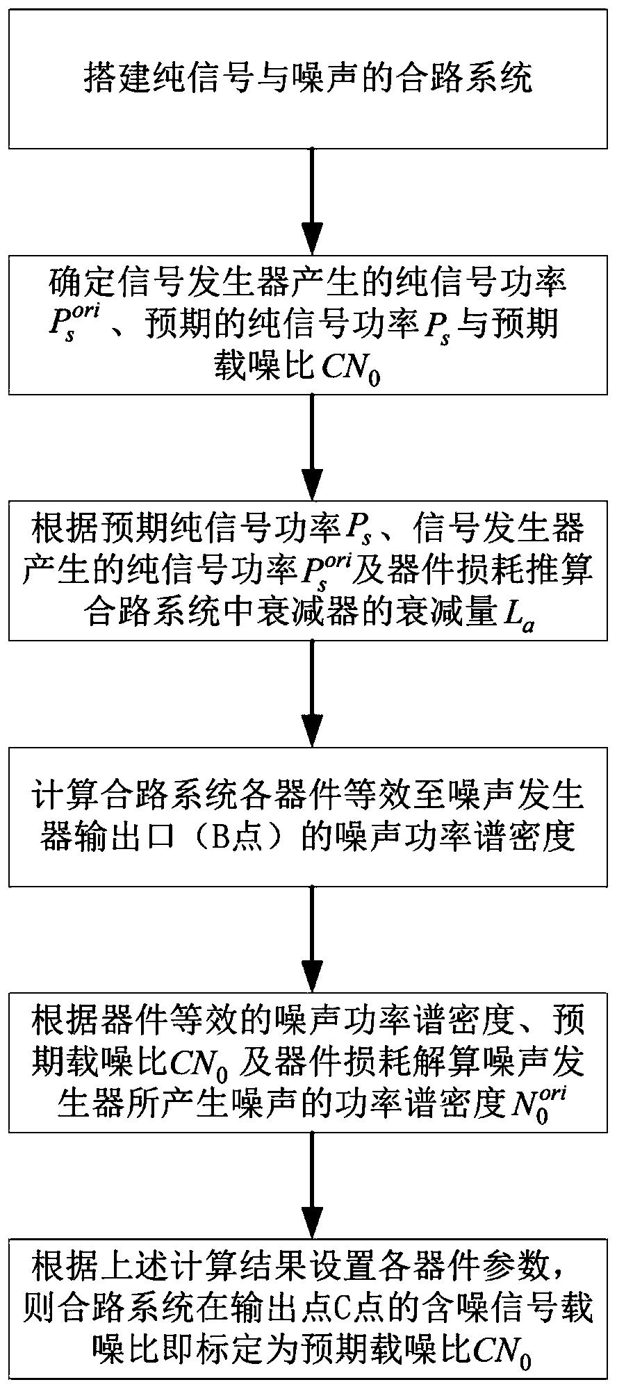
[0036] The carrier-to-noise ratio calibration method of the high-precision fixed signal and noise-changing mode of the present invention, such as figure 1 As shown, follow the steps below:
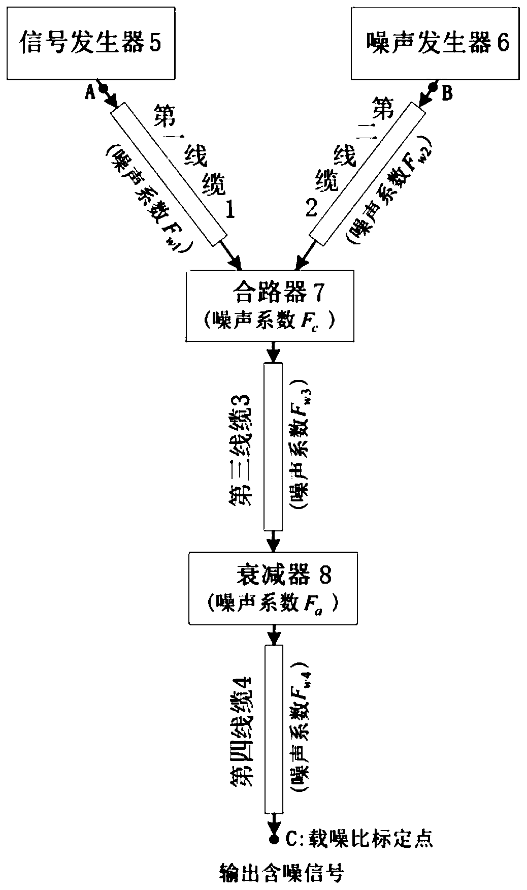
[0037]S1, build a combined system of pure signal and noise, see figure 2 ; The combined system includes a signal generator 5, a noise generator 6, a combiner 7, an attenuator 8, and a coaxial cable, and the output port of the signal generator 5 and the output port of the noise generator 6 pass through the cable respectively Connect with combiner 7, combiner 7 is connected with attenuator 8 through cable; The signal flow in the system is: signal generator 5 produces pure signal (corresponding to figure 2 point A), while the noise generator 6 produces white noise (corresponding to figure 2 point B), the pure signal is input to the combiner 7 through the first cable 1, and the white noise is input to the combiner 7 through the second cable 2, and the noise-containing signal output by the...
PUM
 Abstract
Description
Claims
Application Information