
Current-limiting switch device, system and application

A current-limiting switch, vacuum switch technology, applied in high-voltage/high-current switches, electrical switches, high-voltage air circuit breakers, etc., can solve the problem of limited current-limiting depth, high reactor cost, and large size and weight of current-limiting reactors. problems, to achieve the effect of reducing power loss, high reactance rate, safe and reliable breaking and completing commutation

Inactive Publication Date: 2019-10-18
ANHUI HEKAI ELECTRICAL TECH CO LTD
View PDF3 Cites 0 Cited by
  • Summary
  • Abstract
  • Description
  • Claims
  • Application Information

AI Technical Summary

Problems solved by technology

The winding or copper / aluminum row current-carrying cross-sectional area of ​​this current-limiting reactor requires a large amount, and the volume and weight of the current-limiting reactor are large, resulting in a high cost of the reactor. In order to meet the actual production and on-site installation The feasibility of operation, while considering the cost factor, the reactance rate of this current-limiting reactor can only be within 13%, and the current-limiting depth is limited

Method used


Image

  • Current-limiting switch device, system and application
  • Current-limiting switch device, system and application
  • Current-limiting switch device, system and application

Examples


Embodiment Construction

[0061] Exemplary embodiments of the present disclosure will be described in more detail below with reference to the accompanying drawings. Although exemplary embodiments of the present disclosure are shown in the drawings, it should be understood that the present disclosure may be embodied in various forms and should not be limited by the embodiments set forth herein. Rather, these embodiments are provided for more thorough understanding of the present disclosure and to fully convey the scope of the present disclosure to those skilled in the art.

[0062] Reference will now be made in detail to the exemplary embodiments, examples of which are illustrated in the accompanying drawings. When the following description refers to the accompanying drawings, the same numerals in different drawings refer to the same or similar elements unless otherwise indicated. The implementations described in the following exemplary examples do not represent all implementations consistent with the ...


PUM


Abstract

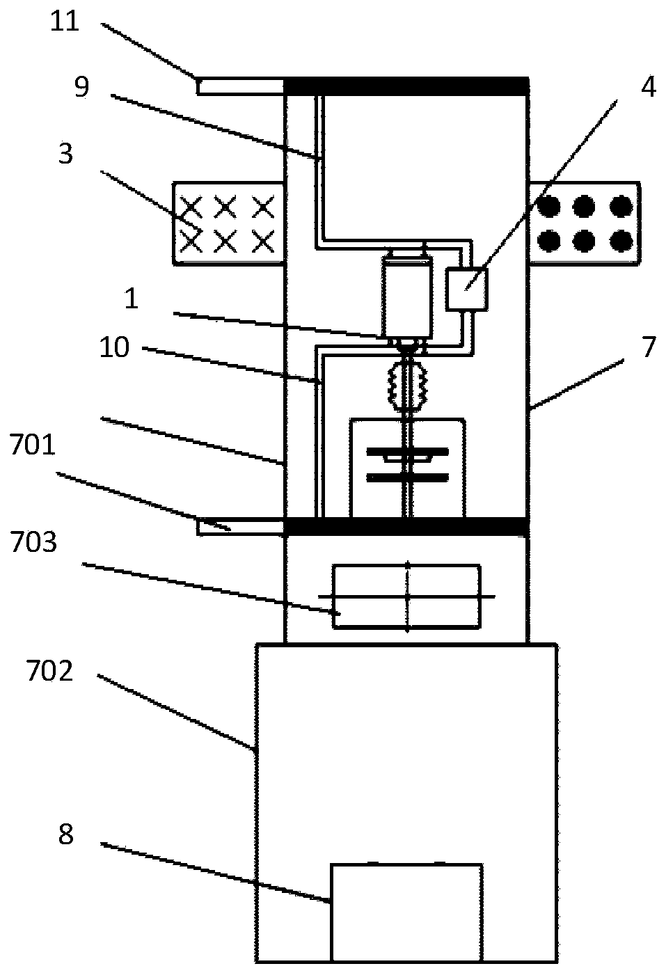
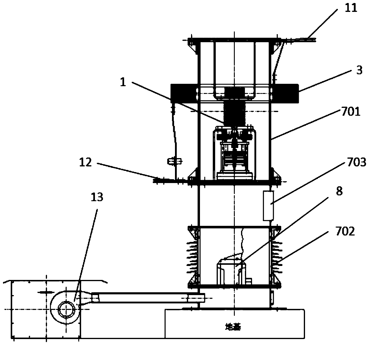
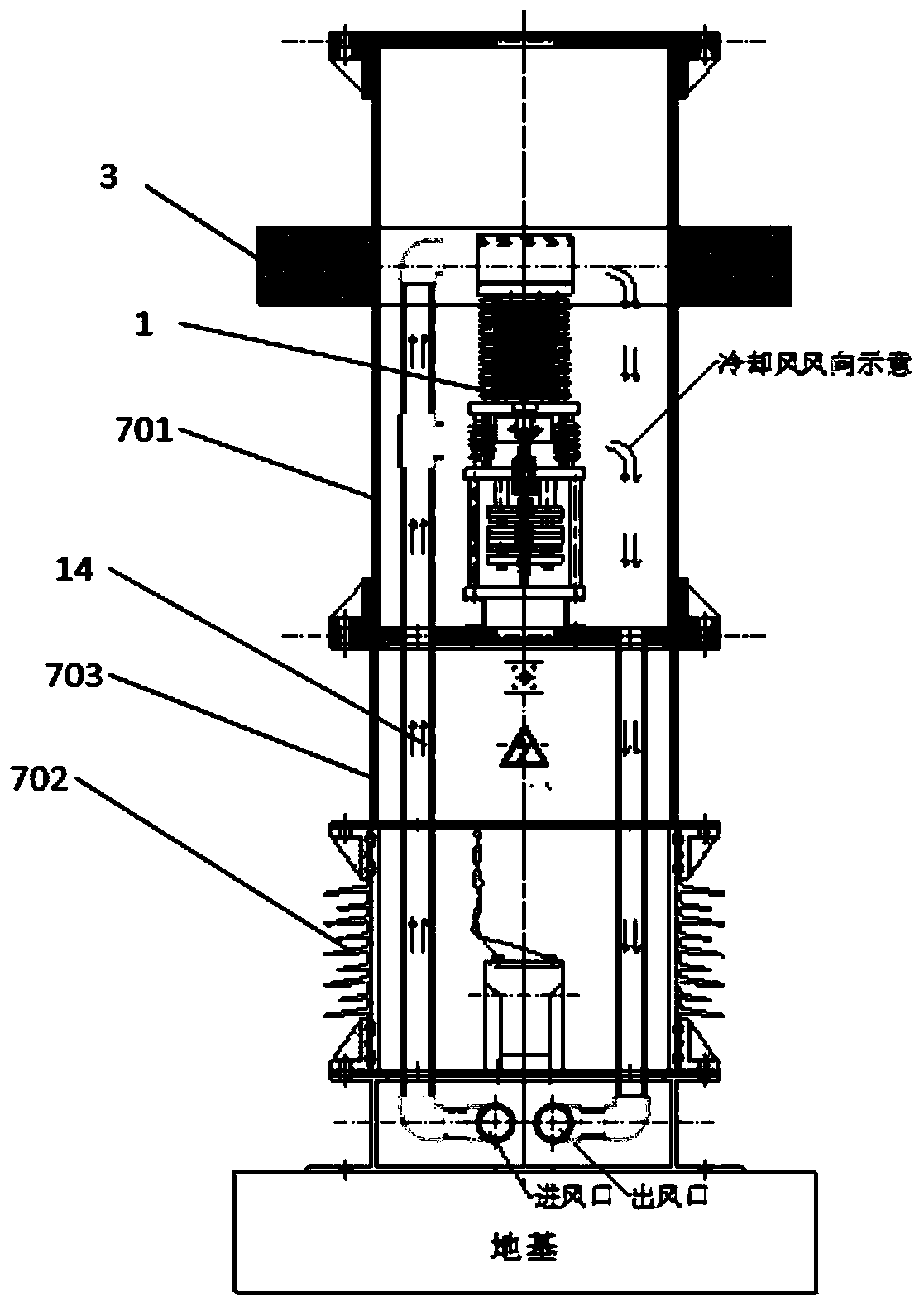
The invention discloses a current-limiting switch device, a system and an application. the current-limiting switch device comprises a vacuum switch, a depth current-limiting reactor, an anti-steepnessenergy absorber, a Rogowski coil, a control module, a switching power supply and an insulating cylinder, wherein the vacuum switch, the anti-steepness energy absorber, the Rogowski coil, the controlmodule and the switching power supply are arranged in the insulating cylinder; the depth current-limiting reactor is arranged on the outer wall of the insulating cylinder; the vacuum switch is connected with the depth current-limiting reactor and the anti-steepness energy absorber in parallel; the switching power supply is connected with the vacuum switch; the Rogowski coil is arranged at the output end of the vacuum switch; the control module is connected with the switching power supply and the Rogowski coil; and the control module is used for receiving a current signal of the Rogowski coil and sending opening and closing signals to the switching power supply. The problems that in the prior art, the vacuum switch is low in opening speed and is difficult in opening and closing during shortcircuit, and the arrangement of the current-limiting reactor is not reasonable are solved.

Description

technical field [0001] The present invention relates to a current limiting switch device, system and application. Background technique [0002] The vacuum switchgear in the prior art has the advantages of small size, light weight, suitable for frequent operation, and no maintenance for arc extinguishing. It is widely used in distribution networks and can be used as electrical equipment in industrial and mining enterprises, power plants, and substations. For protection and control, it is especially suitable for use places that require no oil, less maintenance and frequent operations. The vacuum switchgear can be configured in central cabinets, double-layer cabinets, and fixed cabinets to control and protect high-voltage electrical equipment. The opening time of the vacuum switch of the traditional current-limiting switch device is 30-50ms, and the closing time is 40-60ms. When a short-circuit fault occurs, because the short-circuit current exceeds the breaking capacity of the...

Claims


Application Information

Patent Timeline
IPC IPC(8): H01H9/54H01H33/66
CPCH01H9/54H01H33/66
Inventor 李俭华余振
Owner ANHUI HEKAI ELECTRICAL TECH CO LTD
Learn More