
Ultra-wideband coaxial directional coupler

A directional coupler and ultra-broadband technology, applied in the field of couplers, can solve problems such as high supporting costs, large design limitations, narrow operating frequency of coaxial directional couplers, etc., to achieve elastic contact function, good transmission function, The effect of ensuring stability

Inactive Publication Date: 2019-10-18
CHINA ELECTRONIS TECH INSTR CO LTD
View PDF5 Cites 0 Cited by
  • Summary
  • Abstract
  • Description
  • Claims
  • Application Information

AI Technical Summary

Problems solved by technology

If the ultra-wideband operating frequency index of 100MHz-110GHz is to be realized, the limited number of step changes cannot meet the design requirements
[0003] At present, the coaxial directional coupler that can be applied to 110GHz has a narrow operating frequency, mostly 50GHz-110GHz, which cannot meet the requirements of ultra-wideband use.
This requires the use of multiple coaxial directional couplers for combined design in order to achieve ultra-wideband operating frequencies such as 100MHz-110GHz or 3GHz-110GHz, resulting in relatively large design limitations and high supporting costs

Method used


Image

  • Ultra-wideband coaxial directional coupler
  • Ultra-wideband coaxial directional coupler
  • Ultra-wideband coaxial directional coupler

Examples


Embodiment Construction

[0019] The following will clearly and completely describe the technical solutions in the embodiments of the present invention with reference to the drawings in the embodiments of the present invention.

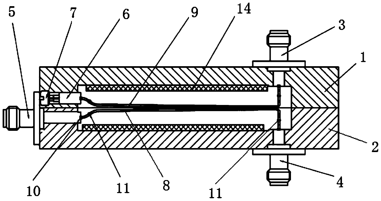
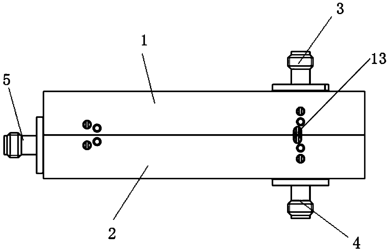
[0020] The invention provides an ultra-broadband coaxial directional coupler, such as figure 1 and figure 2 As shown, the coaxial directional coupler adopts the design scheme of the coupled stripline working principle, extracts power from the main circuit according to a certain ratio and outputs it directionally from the secondary circuit, and realizes the directional coupling function.

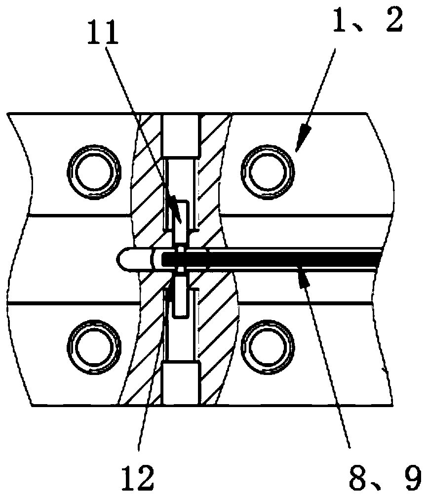
[0021] The ultra-broadband coaxial directional coupler of the present invention includes a coupling cavity, the coupling cavity is divided into an upper cavity 1 and a lower cavity 2, and the two are threaded after being matched with a precision positioning shaft hole, thereby forming the coupling transmission of the coupler cavity. A coaxial coupling connector 3 is arranged on the upper c...


PUM


Abstract

The invention discloses an ultra-wideband coaxial directional coupler. The coupler comprises a coupled cavity; a coaxial input connector, a coaxial output connector and a coaxial coupling connector are arranged on the outer wall of the coupling cavity; a coupling inner conductor and a load are arranged in the coupling cavity; the coupling inner conductor comprises a main path coupling inner conductor and an auxiliary path coupling inner conductor which are distributed in a gradual change line; two ends of the main path coupling inner conductor are respectively connected with the coaxial inputconnector and the coaxial output connector through elastic connecting assemblies, and two ends of the auxiliary path coupling inner conductor are respectively connected with the coaxial coupling connector and a load through elastic connecting assemblies; and the coupling inner conductor is connected with the coupling cavity through a support rod in the longitudinal direction. The coupler disclosedby the invention realizes good coupling, high isolation and high directivity indexes of the coupler in a working frequency range of 100MHz-110GHz. And meanwhile, a fuzz button spring type contact assembly is adopted, so that elastic contact in a small size and a good transmission function can be considered.

Description

technical field [0001] The invention relates to a coupler, in particular to an ultra-wideband coaxial directional coupler. Background technique [0002] Directional couplers are widely used in microwave radio frequency systems, usually for power sampling, isolation, mixing and power monitoring. The directional coupler is generally composed of three parts: the main channel straight-through transmission line, the auxiliary channel coupling line and the coupling structure. The working principle is that the microwave signal is input and output through the direct channel. signal separation. The directional coupler can be divided into various types according to different applications. Among them, the coaxial directional coupler mostly adopts the stripline coupling design structure, and the inner conductor of the secondary coupling needs to be transformed into multiple steps to achieve the broadband index. The length of each step is set is a quarter of the wavelength of the cente...

Claims


Application Information

Patent Timeline
IPC IPC(8): H01P5/18
CPCH01P5/18
Inventor 许晓龙赵广峰刘跃朱战发文春华姜万顺
Owner CHINA ELECTRONIS TECH INSTR CO LTD
Learn More