
Control circuit and control method applied to resonance circuit

A technology of current control circuit and resonant circuit, which is applied in the direction of control/regulation system, high-efficiency power electronic conversion, electrical components, etc., and can solve the problems of low performance of resonant circuit and no more effective solutions

Pending Publication Date: 2019-10-18
INVENTRONICS HANGZHOU
View PDF0 Cites 3 Cited by
  • Summary
  • Abstract
  • Description
  • Claims
  • Application Information

AI Technical Summary

Problems solved by technology

However, when the resonant circuit is working in the hiccup mode, the resonant circuit will have a high output energy, and thus the working performance of the resonant circuit will be very low.
At present, there is no effective solution to this technical problem

Method used


Image

  • Control circuit and control method applied to resonance circuit
  • Control circuit and control method applied to resonance circuit
  • Control circuit and control method applied to resonance circuit

Examples


Embodiment approach

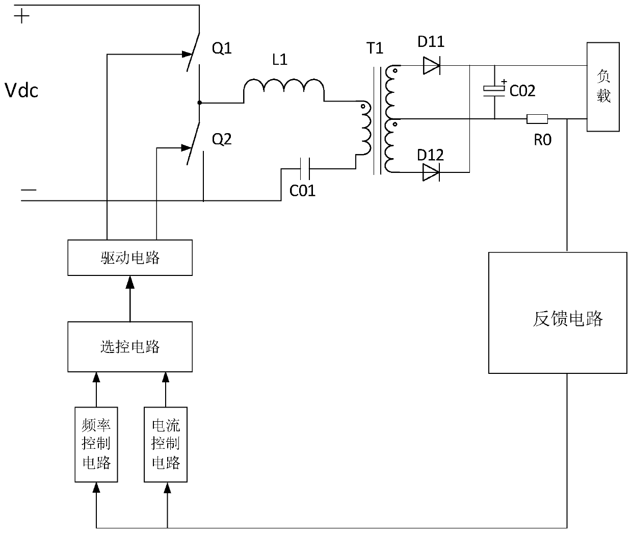
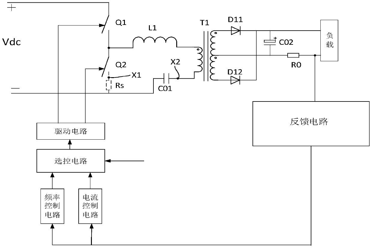
[0057] Based on the above embodiments, this embodiment further explains and optimizes the technical solution, please refer to Figure 5 , Figure 5It is a structural diagram of a current control circuit provided by an embodiment of the present invention. As a preferred implementation manner, the current control circuit is specifically a comparison operation circuit;

[0058] Wherein, the positive-phase input terminal of the comparison operation circuit is used to detect the switching current or resonance current of the resonant circuit in the running state, and the negative-phase input terminal of the comparison operation circuit is used to receive the output signal of the feedback circuit.

[0059] In practical applications, the current control circuit can be set as a comparison operation circuit, because the comparison operation circuit not only has the advantages of simple and reliable calculation logic, but also the cost of the comparison operation circuit is relatively l...


PUM


Abstract

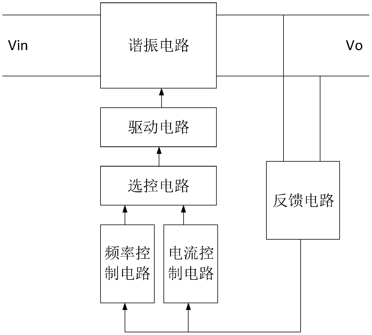
The invention discloses a control circuit applied to a resonance circuit. The control circuit comprises a feedback circuit, a frequency control circuit, a current control circuit, a driving circuit, and a selection and control circuit; the feedback circuit is used for detecting the voltage signals of the output current of the resonance circuit and comparing the voltage signals with preset reference signals, and outputting feedback signals reflecting the magnitude of the output current; the frequency control circuit is used for controlling the resonance circuit to be in a frequency control modeaccording to the feedback signals; the current control circuit is used for controlling the resonance circuit to be in a current control mode according to the feedback signals; the driving circuit isused for providing driving signals for the resonance circuit according to control signals outputted by the frequency control circuit or the current control circuit; the selection and control circuit is used for comparing monitoring signals generated by a monitoring end with a preset threshold value, controlling the frequency control circuit to work when the monitoring signals are larger than the preset threshold value, or controlling the current control circuit to work when the monitoring signals are smaller than or equal to the preset threshold value. With the control circuit adopted, the problem that the output energy of the resonance circuit is too high in the prior art can be solved.

Description

technical field [0001] The invention relates to the technical field of power electronics, in particular to a control circuit and method applied to a resonant circuit. Background technique [0002] Because the resonant circuit can reduce the switching loss of the driving power supply and improve the efficiency and power density of the power converter, the resonant circuit has been widely used in real life. Wherein, the resonant control circuit detects the output current of the resonant circuit and controls the switching frequency of the resonant circuit according to the frequency control circuit inside the resonant circuit, so that the output current of the resonant circuit remains constant. When the output signal of the resonant circuit gradually decreases, the switching frequency of the resonant circuit will increase. At this time, in order to prevent the output frequency of the resonant circuit from changing too much, the resonant circuit will be controlled to work in hicc...

Claims


Application Information

Patent Timeline
IPC IPC(8): H02M3/335
CPCH02M3/33569Y02B70/10
Inventor 姜德来
Owner INVENTRONICS HANGZHOU
Learn More