Underground parking lot charging pile protection system
An underground parking lot and protection system technology, which is applied in the field of underground parking lot charging pile protection system, can solve problems such as damage, single function, and inability to prevent flooding
- Summary
- Abstract
- Description
- Claims
- Application Information
AI Technical Summary
Problems solved by technology
Method used
Image


Examples
Embodiment 1
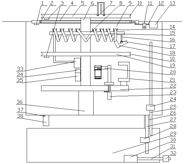
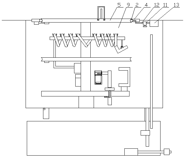
[0042] Embodiment 1. The present invention provides a protection system for charging piles in an underground parking lot, which includes an equipment chamber 9 arranged under the ground, an opening 4 is provided at the top of the equipment chamber 9, and a lifting mechanism 36 is provided at the bottom of the equipment chamber 9. The upper end of the lifting mechanism 36 is provided with a column 6, the lower end of the column 6 is provided with a workbench 22, the overall control mechanism is arranged on the workbench 22, the middle part of the column 6 is provided with a sealing bottom plate 19, and the sealing bottom plate 19 is provided above Charging mechanism, the top of the column 6 is provided with a sealed top plate 5, and the equipment chamber 9 is provided with a humidity monitoring mechanism, a lifting calibration mechanism and a water level monitoring mechanism. , the lifting mechanism 36, and the charging mechanism are connected, and the general control mechanism ...
Embodiment 2
[0048] The difference between this embodiment and Embodiment 1 is:
[0049] The opening 4, the sealing top plate 5, and the sealing bottom plate 19 are circular, and the inside of the opening 4 is provided with a sealing mechanism, and the edge sides of the sealing top plate 5 and the sealing bottom plate 19 are provided with an annular groove 10.
[0050] The sealing mechanism comprises an end-to-end annular airbag 2 arranged on the inner edge of the opening 4, the vertical section of the airbag 2 is circular, and the airbag 2 communicates with the air pump 13 arranged in the equipment cavity 9 through the air supply pipeline 12, The air supply pipeline 12 is provided with a first electromagnetic valve 11 , and the first electromagnetic valve 11 and the air pump 13 are connected with a microcontroller 35 . The annular groove mainly cooperates with the annular air bag here to realize sealing. One side of the annular airbag is directly bonded to the side wall of the opening. T...
Embodiment 3
[0053] The difference between this embodiment and Embodiment 1 is:
[0054]The humidity monitoring mechanism includes a humidity sensor arranged in the equipment cavity 9 and a dehumidification mechanism 20 for dehumidification. The dehumidification mechanism 20 includes an L-shaped bracket 46 arranged on the workbench 22, and the upper end of the L-shaped bracket 46 The upper cylinder 44 is vertically arranged, the inside of the upper cylinder 44 is provided with a micro fan 45, the lower end of the upper cylinder 44 is screwed to the lower cylinder 48, the upper end of the lower cylinder 48 is provided with a first filter screen 47, and the lower cylinder 48 is provided with a first filter screen 47. The second filter screen 50 is movable at the lower end of 48, and the color-changing silica gel 49 is arranged between the first filter screen 47 and the second filter screen 50. The lower cylinder 48 is made of a transparent material, and the humidity sensor and the miniature f...
PUM
 Abstract
Description
Claims
Application Information
 - R&D
- Intellectual Property
- Life Sciences
- Materials
- Tech Scout
- Unparalleled Data Quality
- Higher Quality Content
- 60% Fewer Hallucinations
Browse by: Latest US Patents, China's latest patents, Technical Efficacy Thesaurus, Application Domain, Technology Topic, Popular Technical Reports.
© 2025 PatSnap. All rights reserved.Legal|Privacy policy|Modern Slavery Act Transparency Statement|Sitemap|About US| Contact US: help@patsnap.com