Bionic robot fish oriented to environment monitoring

A technology of environmental monitoring and robotic fish, applied to instruments, non-electric variable control, control/regulation systems, etc., can solve problems such as cost or long construction period, and achieve the effect of shortening the research and development period, reducing development costs, and reducing repeated designs

Pending Publication Date: 2019-10-22
INST OF AUTOMATION CHINESE ACAD OF SCI
View PDF0 Cites 8 Cited by
  • Summary
  • Abstract
  • Description
  • Claims
  • Application Information

AI Technical Summary

Problems solved by technology

[0003] At present, most of the water quality monitoring is to set monitoring sensors at some fixed points. To understand the water environment of a river or a lake in detail, it is necessary to set up many points, so that both the cost and the construction period will be relatively long.

Method used


Image

  • Bionic robot fish oriented to environment monitoring
  • Bionic robot fish oriented to environment monitoring
  • Bionic robot fish oriented to environment monitoring

Examples


Embodiment 1

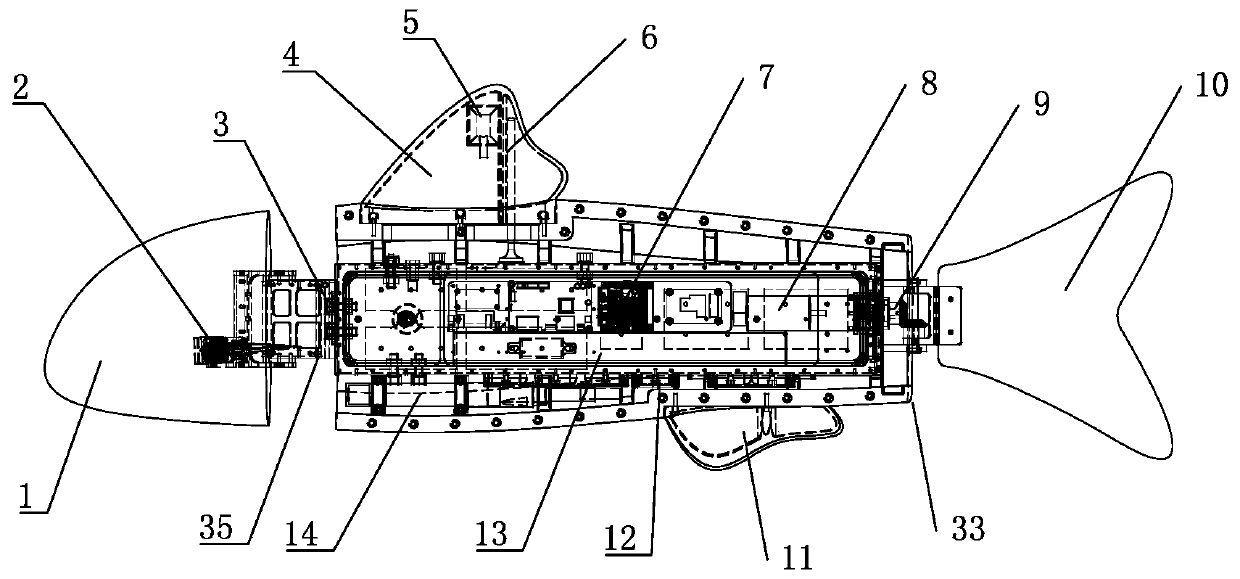
[0036] see Figure 1 to Figure 2 , the present embodiment is a bionic robotic fish for environment monitoring, comprising a fish body 33 provided with a counterweight module 12, a fish head mounted on the front end of the fish body and provided with a pitching module 2 and a left and right turning module 3, and a swimming module 9 are installed in the caudal fin 10 of fish body tail end, are installed in the dorsal fin 4 of fish body back, are installed in the pelvic fin 11 of fish body abdomen.

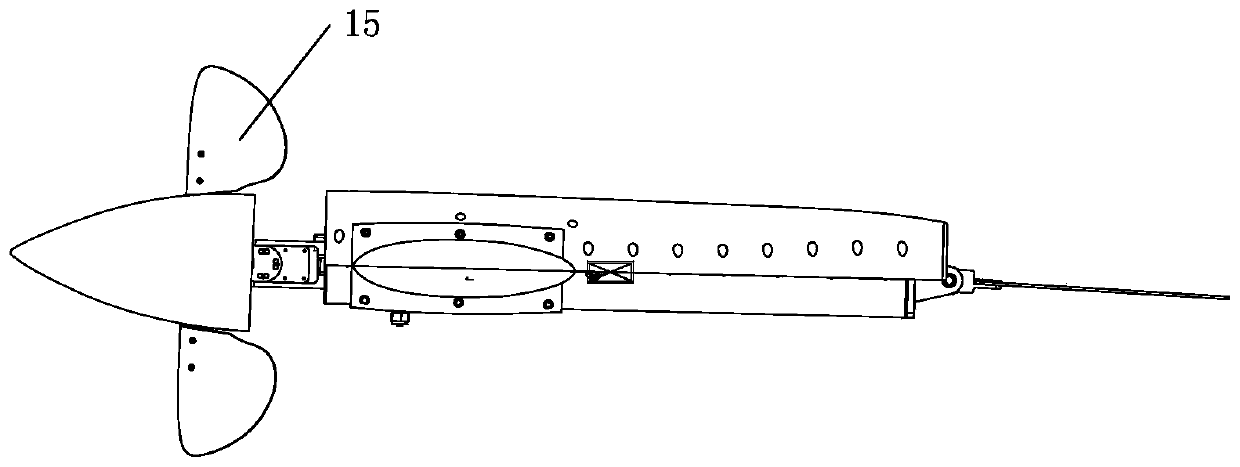
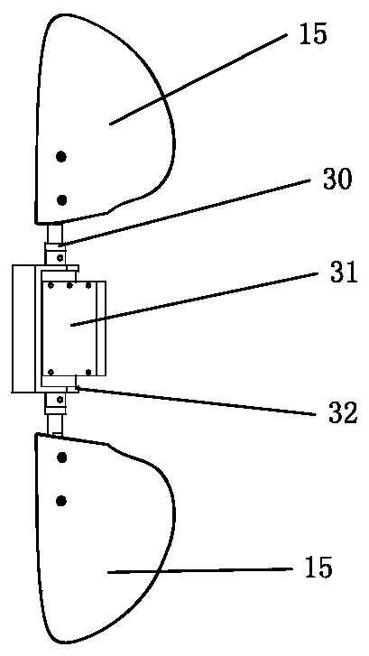
[0037] see figure 2 and image 3, the pitching module 2 shown is used to control the floating and diving of the robotic fish, including two pectoral fins 15 arranged symmetrically on both sides of the fish head 1 and controlling the floating and diving of the robotic fish by adjusting its own direction, and the floating fins 15 installed inside the fish head. The submersible frame 32 and the second steering gear 31 installed in the floating and submerging frame 32, the two ends of...

Embodiment 2

[0045] see Figure 1 to Figure 2 , the present embodiment is a bionic robotic fish for environment monitoring, comprising a fish body 33 provided with a counterweight module 12, a fish head mounted on the front end of the fish body and provided with a pitching module 2 and a left and right turning module 3, and a swimming module 9 are installed in the caudal fin 10 of fish body tail end, are installed in the dorsal fin 4 of fish body back, are installed in the pelvic fin 11 of fish body abdomen. The difference between this embodiment and the first embodiment is only: the pitching module and the left and right turning modules, and the rest are the same and will not be repeated.

[0046] see Figure 10 , Figure 11 In this embodiment, the left and right turning module includes a swing section 34, a third swing device 37 located in the swing section 34 and used to connect with the fish body, the structure of the third swing device 37 is the same as that of the first swing devic...


PUM


Abstract

A bionic robot fish oriented to environment monitoring comprises a fish body, a fish head, a caudal fin, a dorsal fin and a ventral fin, wherein the fish body is provided with a counterweight module and a battery; the fish head is mounted on one end of the fish body; the fish head is provided with a pitching module for controlling the upward floating and downward diving of the robot fish and a left and right turning module for changing the swimming direction of the robot fish; the caudal fin is mounted on the other end of the fish body through a swimming module; the dorsal fin is mounted at the dorsum of the fish body; and the ventral fin is mounted at the ventral side of the fish body. The bionic robot fish oriented to environment monitoring can detect multiple parameters such as pH values, solubility, temperature, ammonia nitrogen content, electrical conductivity, water hardness, turbidity and the like in different waters in real time. The bionic robot fish can cruise according to apredetermined path and detect water quality data of positions in the predetermined path. In addition, the bionic robot fish adopts a modular design in mechanical design, thereby reducing repeated design and repeated processing, decreasing relevant development cost, and shortening the research and development period.

Description

technical field [0001] The invention relates to the technical field of underwater bionic robot fish, in particular to a bionic robot fish oriented to environment monitoring. Background technique [0002] As humans pay more and more attention to the development of marine resources, the demand for related marine equipment is increasing, and underwater robots are widely used in various fields of exploring the ocean. As an important branch of underwater robots, bionic robot fish has also been flourishing. The bionic robot fish combines various technologies such as bionics, mechanical design, materials science, and control disciplines. At present, the bionic robot fish is mostly used for scientific research and popular science exhibitions, but less for life and production, especially for water quality monitoring of rivers, lakes, oceans and other water environments. [0003] At present, most of the water quality monitoring is to set monitoring sensors at certain fixed points. T...

Claims


Application Information

Patent Timeline
Patent Type & Authority Applications(China)
IPC IPC(8): B63C11/52G01D21/02G05D1/02
CPCB63C11/52G01D21/02G05D1/0206
Inventor 王宇王睿王硕谭民段小广魏金辉王颖
Owner INST OF AUTOMATION CHINESE ACAD OF SCI
Why Eureka
Try Eureka