Automatic continuous packaging machine

A packaging machine and automatic technology, applied in packaging, transport packaging, packaging protection, etc., can solve the problems of small consumption radius, reduce production efficiency, increase production cost, etc., and achieve the effect of smooth transportation, convenient observation and low failure rate

Active Publication Date: 2019-10-22
QINGDAO HAINUO BIOLOGICAL ENG
View PDF9 Cites 1 Cited by
  • Summary
  • Abstract
  • Description
  • Claims
  • Application Information

AI Technical Summary

Problems solved by technology

When the packaging machine of this structure transports the medicine belt and the packaging film, the driving force is provided by the driving roller, and the driving roller exerts a constant torque to drive the medicine belt or the packaging film, and the medicine belt or the packaging film transmits the rotational torque to the reel, thereby Drive the reel to rotate, but the torque is constant during the whole packaging process, but the reel is getting smaller and smaller due to the consumption radius of the medicine tape or packaging film, and the pulling force on the reel is getting larger and larger, so that the medicine tape or packaging film is rewound more and more The tighter it is, the more often there will be conveying failures in the packaging process, and manual adjustments will be required, which will reduce production efficiency and increase production costs

Method used


Image

  • Automatic continuous packaging machine
  • Automatic continuous packaging machine
  • Automatic continuous packaging machine

Examples


Embodiment Construction

[0043] The present invention will be described in further detail below in combination with specific embodiments.

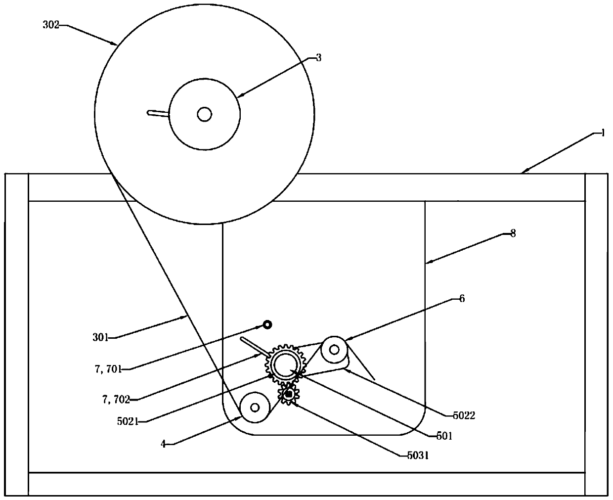
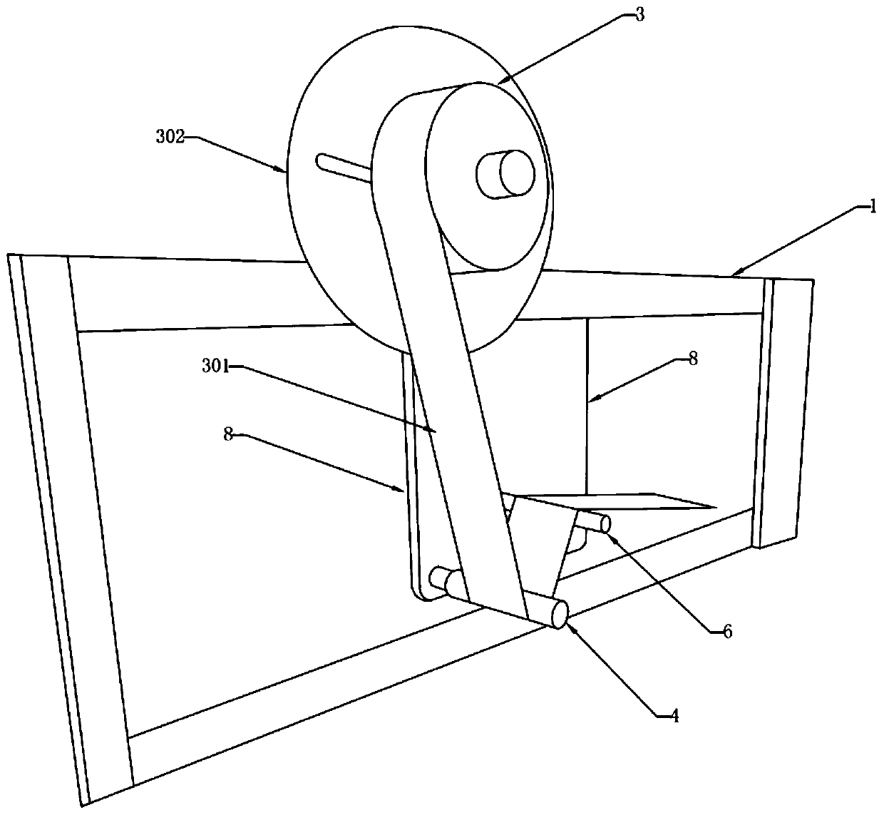
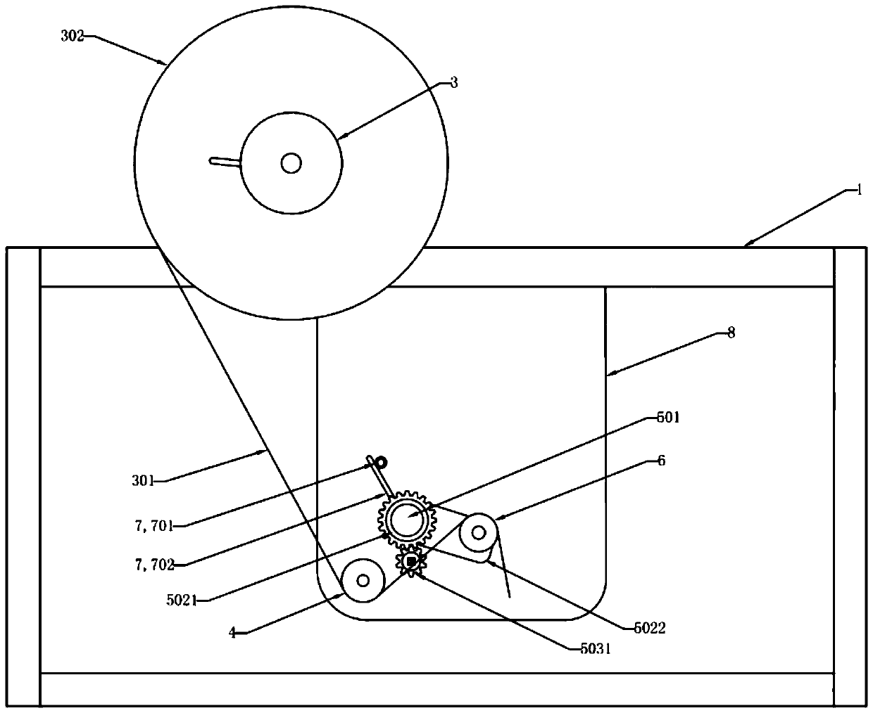
[0044] figure 1 and figure 2 Shown are the structural schematic diagrams of the automatic continuous packaging machine in Embodiment 1 of the present invention under two viewing angles. The automatic continuous packaging machine shown in Embodiment 1 of the present invention includes a frame 1, a first driving motor 2, a paper reel 3, a static roller 4, a power unit 5, a moving roller 6 and a position sensor 7; the first driving The motor 2 is arranged on the frame 1 , the paper roll 3 is connected to the first driving motor 2 ; the static roller 4 is arranged on the frame 1 . The power unit 5 is fixedly arranged on the frame 1, the moving roller 6 is connected with the power unit 5, the reel 3, the static roller 4 and the movable roller 6 are all arranged at intervals, and the belt body 301 protruding from the reel 3 , around the outside of the static roller ...


PUM


Abstract

The invention provides an automatic continuous packaging machine which comprises a frame, a first driving motor, a paper winding cylinder, a static roller, a power unit, a movable roller and a position sensor; the movable roller, the static roller and the paper winding cylinder are arranged at intervals; and the movable roller has a first limit position and a second limit position in the moving direction of the movable roller, the first driving motor is in a starting state when the movable roller is in the first limit position, a belt body extends out of the paper winding cylinder and is conveyed, and the first driving motor is in a stopping state when the movable roller is in the second limit position. The belt body conveying speed of the packaging machine can be adjusted according to theaction speed of the driving motor and the movable roller, the tension borne by the belt body in the packaging process is small and relatively constant, the belt body can be conveyed smoothly withoutbecoming tighter and tighter in the conveying process, the failure rate is low, and manual intervention is not needed.

Description

technical field [0001] The invention belongs to the technical field of packaging machinery, in particular to an automatic continuous packaging machine. Background technique [0002] In order to facilitate use and ensure cleanliness and sterility, medical dressings are usually cut into sheets according to certain specifications, and then packaged in individual small packages. When used, the packaging bag is opened and taken out for use. With the improvement of medical level, the composition of medical dressings has gradually developed into a structure with multiple functional layers, and the packaging process of products is more complicated. At present, when this product is packaged, the packaged wrapping paper and the functional layers of the dressing are simultaneously unwound and transported to each process for continuous cutting and lamination packaging to achieve continuous production. [0003] Chinese patent 200420067256.6 discloses a PU dressing patch packaging machin...

Claims


Application Information

Patent Timeline
Patent Type & Authority Applications(China)
IPC IPC(8): B65B41/16B65H16/10B65H23/192B65H20/02B65B57/02
CPCB65B41/16B65B57/02B65H16/10B65H20/02B65H23/192B65H2403/92
Inventor 葛坤于世杰金亮亮赵宇庆
Owner QINGDAO HAINUO BIOLOGICAL ENG
Why Eureka
Try Eureka