an air motor

An air motor and air hole technology, applied in the direction of engine components, machines/engines, engine sealing devices, etc., can solve problems such as unstable output torque, failure to start, unstable speed, etc., to achieve stable output torque and speed, and working conditions Simple, smooth rotating effect

Active Publication Date: 2021-01-05
顾新钿
View PDF28 Cites 0 Cited by
  • Summary
  • Abstract
  • Description
  • Claims
  • Application Information

AI Technical Summary

Problems solved by technology

[0005] For this reason, the embodiment of the present invention provides an air motor to solve the problems in the prior art that the output torque is unstable, the rotating speed is unstable, and even cannot be started due to the complex working conditions of the blades.

Method used


Image

  • an air motor
  • an air motor
  • an air motor

Examples


Embodiment 1

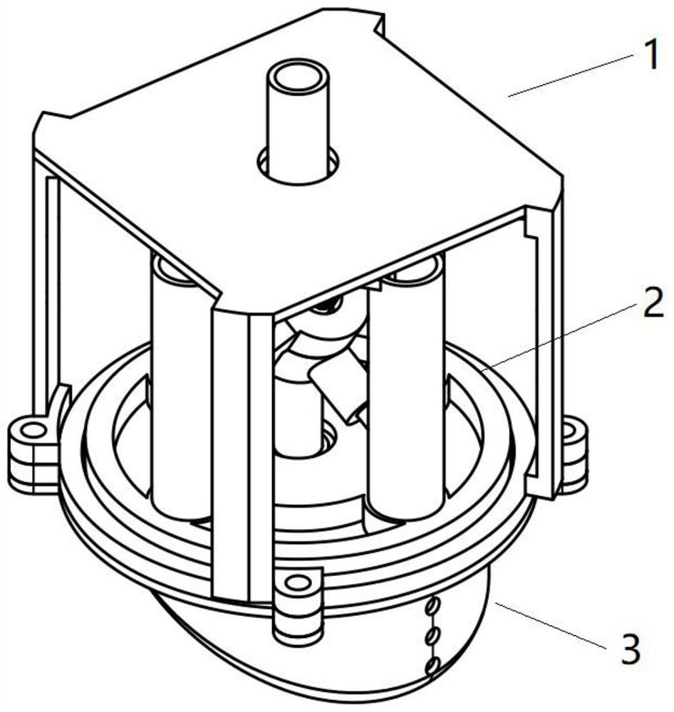
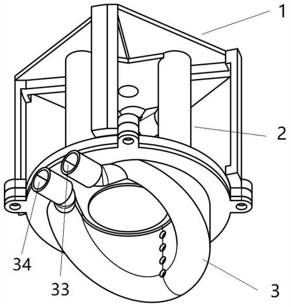
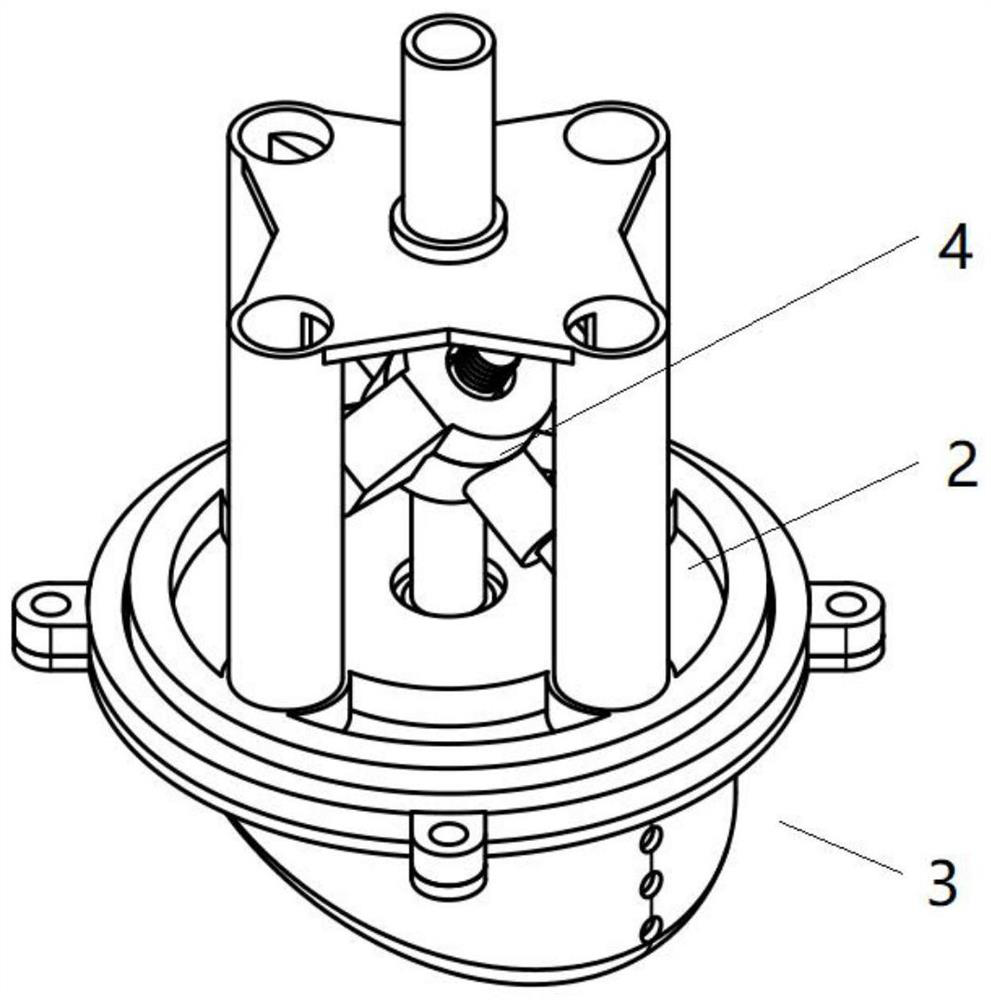
[0048] Such as Figure 1-12 As shown, Embodiment 1 provides an air motor, which includes a frame 1 , a rotor 2 , a cylinder 3 , a swash plate 4 and a paddle rod 5 .

[0049] An installation space is provided inside the frame 1 , a first shaft hole 11 is provided at one end of the frame 1 , fifth bearings are provided at both ends of the first shaft hole 11 , and the other end of the frame 1 is an open structure. Specifically, the frame 1 includes a mounting plate 12 and a plurality of mounting columns 13, the mounting columns 13 are evenly fixed on the edge of the mounting plate 12, and the multiple mounting columns 13 are located on the same side of the mounting plate 12, and the mounting columns 13 are far away from One end of the mounting plate 12 is provided with a lug 14 for connecting the cylinder body 3 , and the first shaft hole 11 is located at the center of the mounting plate 12 .

[0050] The rotor 2 includes a cylinder head 21 , a cover plate 22 , an output shaft ...


PUM


Abstract

The embodiment of the invention discloses a pneumatic motor, and relates to the technical field of power equipment. The pneumatic motor comprises a machine frame, a rotor, a cylinder body, a swash plate and a paddle rod, wherein the rotor is arranged in the machine frame, and the rotor is provided with a threading hole; the cylinder body is arranged outside the machine frame, an air flow groove isformed in the cylinder body, and an inclined fixed shaft perpendicular to the air flow groove is arranged on the end face of the cylinder body; the depth from the two ends of the air flow groove to the middle of the air flow groove is gradually deepened, and the swash plate is fixed on the inclined fixed shaft; and the paddle rod is slidably arranged in the threading hole, one end of the paddle rod is connected with a fisheye slide rod of the swash plate, and the other end of the paddle rod is located in the air flow groove. The pneumatic motor has the advantages that the working condition issimple, the situations that the sealing becomes poor or invalid, and the pneumatic motor even cannot be started cannot appear, and the output torque and the rotating speed are stable.

Description

technical field [0001] The embodiment of the present invention relates to the technical field of power equipment, in particular to an air motor. Background technique [0002] Pneumatic motor, also known as wind motor, refers to a device that converts the pressure energy of compressed air into rotational mechanical energy, and is generally used as a rotational power source for more complex devices or machines. Existing air motors are divided into vane air motors and piston air motors according to their structures. [0003] When the vane air motor is ventilated, a small part of the gas acts on the bottom of the vane through the vent hole at the bottom of the vane slot, causing the vane to pop out and press against the wall of the stator cavity; some springs are installed at the bottom of the vane slot to promote the vane to pop out. When rotating, the blades are tightly pressed against the wall of the stator cavity under the action of centrifugal force to form a seal. The bl...

Claims


Application Information

Patent Timeline
Patent Type & Authority Patents(China)
IPC IPC(8): F01C1/00F01C21/08F01C21/10F01C21/18F01C19/00
CPCF01C1/00F01C19/00F01C21/08F01C21/10F01C21/104F01C21/18
Inventor 顾新钿
Owner 顾新钿
Why Eureka
Try Eureka