Kitchen air adjusting system

An air conditioning system and air conditioning technology, applied in air conditioning systems, ventilation systems, high-efficiency conditioning technology, etc., can solve problems such as ineffective use of heat, unfavorable energy conservation and emission reduction, and overall lack of aesthetics.

Active Publication Date: 2019-10-22
NINGBO FOTILE KITCHEN WARE CO LTD
View PDF7 Cites 0 Cited by
  • Summary
  • Abstract
  • Description
  • Claims
  • Application Information

AI Technical Summary

Problems solved by technology

The basic form of the existing kitchen air conditioner is not much different from that of ordinary air conditioners. There are generally two forms. One is the split type of the internal and external units, that is, the external unit is located outdoors, and the internal unit is located indoors. The internal and external units each have a motor fan. The connection method of the kitchen air conditioner with separate indoor and outdoor units needs to be connected through pipelines, and holes need to be opened on the wall, which will damage the decoration. An external unit needs to be hung outside. The structure is not compact enough, and the overall appearance is not beautiful enough.
Moreover, the existing kitchen air conditioners are not rich in functional modes. There are only two modes of cooling and heating. The heat generated during the use of the air conditioner cannot be effectively used, which is not conducive to energy saving and emission reduction, and is also not conducive to improving the energy efficiency of the air conditioner.
[0003] In addition, after the range hood is used for a long time, the volute and impeller of the fan will be stained with a lot of grease. If it is not cleaned effectively, the effect of the range hood and the service life of the fan will be greatly reduced. Although, there are currently special cleaning devices for the fan. The impeller is cleaned, but these cleaning devices are not combined with the kitchen air conditioner

Method used


Image

  • Kitchen air adjusting system
  • Kitchen air adjusting system
  • Kitchen air adjusting system

Examples


Embodiment Construction

[0019] The present invention will be further described in detail below in conjunction with the accompanying drawings and embodiments.

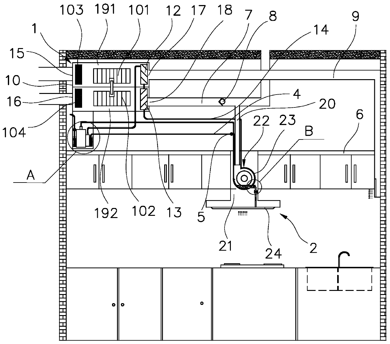
[0020] Such as Figure 1 to Figure 3 As shown, the kitchen air-conditioning system in this embodiment includes main components such as an air-conditioning assembly 1 , a range fume assembly 2 , and a water tank 3 .

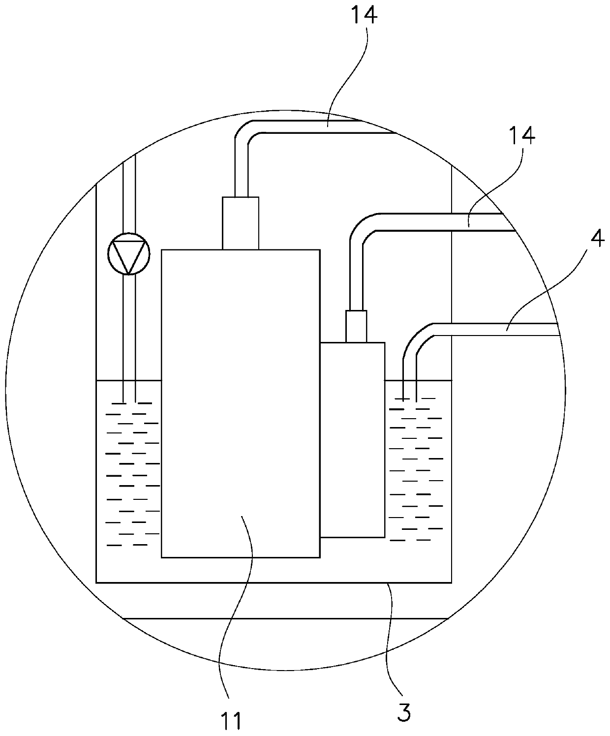
[0021] The air conditioning assembly 1 of this embodiment includes a compressor 11, a first heat exchanger 12 and a second heat exchanger 13, and a refrigerant pipeline is passed between the compressor 11, the first heat exchanger 12 and the second heat exchanger 13 14 are connected, and a four-way valve (not shown in the figure) is installed on the refrigerant pipeline 14. By switching the four-way valve, the switching of the air conditioner working mode is performed. The working principle of the air conditioning assembly 1 is the same as that of the existing air conditioner. Here No more descriptions.

[0022] The air conditio...


PUM


Abstract

The invention discloses a kitchen air adjusting system which comprises an air adjusting assembly and a cooking fume sucking assembly. A compressor, a first heat exchanger and a second heat exchanger of the air adjusting assembly communicate with one another through a refrigerant pipeline. The cooking fume sucking assembly comprises an exhaust hood. The exhaust hood comprises a machine shell, a draught fan is installed in the machine shell and is provided with a volute, and an oil cup is installed at the bottom of the machine shell. The kitchen air adjusting system is characterized by further comprising a water tank containing water, the compressor is immersed in the water tank, the water tank communicates with the interior of the volute through a water pipe, a water pump is installed on the water pipe, a water outlet is formed in the volute, and the water outlet communicates with the oil up through a water draining pipe. The kitchen air adjusting system has the beneficial effects thatwhen the kitchen air adjusting system works, a large amount of heat dissipated by the compressor can make the water temperature in the water tank increased, high-temperature water is conveyed into thevolute under the effect of the water pump, the bottom of an impeller enters water in the volute, the impeller rotates so that the self cleaning purpose can be achieved, and dirt water obtained aftercleaning can be drained into the oil cup.

Description

technical field [0001] The invention relates to a kitchen air conditioning system. Background technique [0002] The kitchen is the main place for people to cook. The quality of the air environment in the kitchen directly affects the mood of the cook. Especially in the hot summer, the sultry environment in the kitchen brings great discomfort to the cook. For this reason, people invented A variety of kitchen air conditioners have been installed to cool down the kitchen air. The basic form of the existing kitchen air conditioner is not much different from that of ordinary air conditioners. There are generally two forms. One is the split type of the internal and external units, that is, the external unit is located outdoors, and the internal unit is located indoors. The internal and external units each have a motor fan. The connection method of kitchen air conditioners with separate indoor and outdoor units needs to be connected through pipelines, and holes need to be drilled ...

Claims


Application Information

Patent Timeline
Patent Type & Authority Applications(China)
IPC IPC(8): F24C15/20F24F7/00F25B9/04
CPCF24F7/06F24F5/001F24F5/0096F24F3/16F24F12/006F24F13/0604F24F13/30F24F13/28F24F11/74F24C15/20F24F2221/10F24F7/00F25B9/04F24F2110/30F24F13/068F24F13/075F24F13/0218F24F8/10Y02B30/70
Inventor 朱启惠曹亚裙余丙松郭俊杰李昂傅海峰崔腾飞赵艳凤
Owner NINGBO FOTILE KITCHEN WARE CO LTD
Why Eureka
Try Eureka