Machining iron scrap treatment equipment

A processing equipment and machining technology, applied in metal processing equipment, metal processing machinery parts, manufacturing tools, etc., can solve the problems of waste of coolant, influence of iron filings on sale, and failure of coolant to be filtered out, so as to promote separation Efficiency, the effect of improving separation efficiency

Inactive Publication Date: 2021-11-26
杨丰年
View PDF0 Cites 5 Cited by
  • Summary
  • Abstract
  • Description
  • Claims
  • Application Information

AI Technical Summary

Problems solved by technology

[0002] Machining refers to the process of changing the shape or performance of the workpiece through a mechanical device. In machining, coolant is required, and there will be a certain amount of coolant in the iron filings generated during cutting. Recycling will generate waste, and it will also have a certain impact on the sale of iron filings
[0003] Existing processing equipment for machining iron filings generally separates coolant and iron filings by filtering, but since there are large gaps between the iron filings when they accumulate, there will be a certain amount of coolant in the gaps between the iron filings It cannot be filtered out, resulting in waste of coolant, and the separation efficiency of iron filings and coolant is low. Therefore, we propose a machined iron filings processing equipment

Method used


Image

  • Machining iron scrap treatment equipment
  • Machining iron scrap treatment equipment
  • Machining iron scrap treatment equipment

Examples


Embodiment Construction

[0028] The following will clearly and completely describe the technical solutions in the embodiments of the present invention with reference to the accompanying drawings in the embodiments of the present invention. Obviously, the described embodiments are only some, not all, embodiments of the present invention.

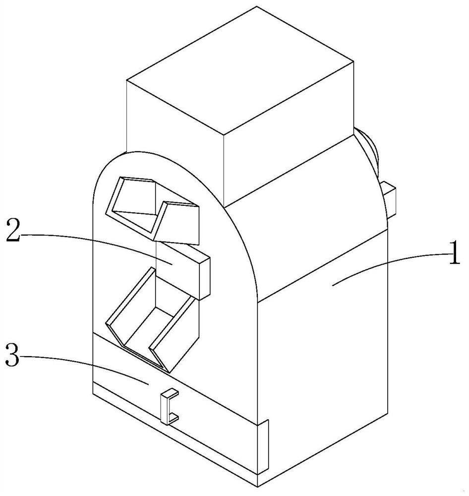
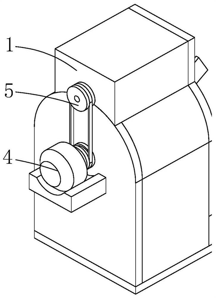
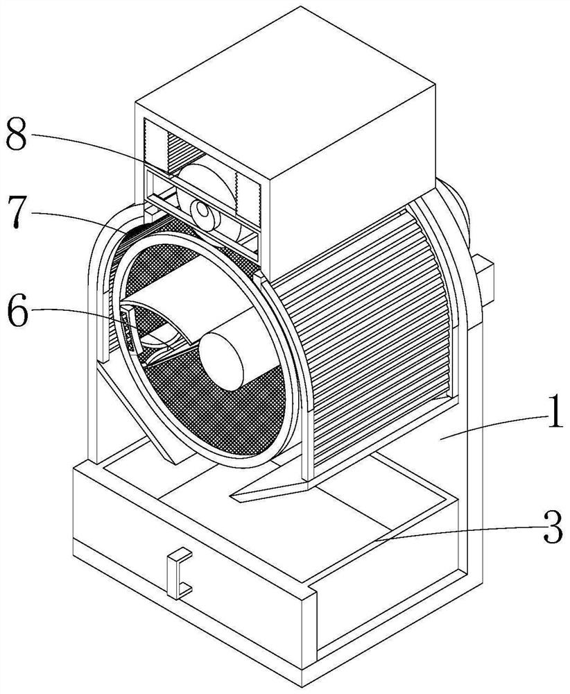
[0029] see Figure 1-9 , the present invention provides a technical solution: a machined iron filings processing equipment, including a main body 1, an energization controller 2 is fixed on the front of the main body 1, and a feed inlet and a feeder are respectively arranged above and below the energization controller 2. Outlet, the liquid collection box 3 is slidingly installed under the front of the equipment main body 1, and the motor 4 is fixed on the back of the equipment main body 1. The output shaft of the motor 4 extends to the inside of the equipment main body 1 and is rotatably installed on the back of the equipment main body 1. The interior of the equipmen...


PUM


Abstract

The invention discloses machining iron scrap treatment equipment, and relates to the technical field of machining. The equipment comprises an equipment main body, wherein a power-on controller is fixed to the front surface of the equipment main body; a liquid collecting box is mounted below the front surface of the equipment main body in a sliding manner; a motor is fixed to the back face of the equipment main body; a filtering mechanism used for separating iron scraps from cutting liquid is arranged in the equipment main body; an anti-splashing mechanism used for preventing the cutting fluid from splashing is arranged on the inner wall of the equipment main body; and a cleaning mechanism used for cleaning the filtering mechanism is arranged at the top of the filtering mechanism. Through the arrangement of an electromagnet, the cutting fluid in the iron scraps is separated from the iron scraps under the inertia that the iron scraps are bounced by a bouncing plate and the attraction effect of the electromagnet on the iron scraps, so that the problem that a certain amount of cooling fluid exists in the gaps of the iron scraps and cannot be filtered out, so that the cooling fluid is wasted is solved. Therefore, the efficiency of separating the iron scraps from the cutting fluid is improved.

Description

technical field [0001] The invention relates to the technical field of mechanical processing, in particular to a processing equipment for machining iron filings. Background technique [0002] Machining refers to the process of changing the shape or performance of the workpiece through a mechanical device. In machining, coolant is required, and there will be a certain amount of coolant in the iron filings generated during cutting. Recycling will generate waste, and it will also have a certain impact on the sale of iron filings. [0003] Existing processing equipment for machining iron filings generally separates coolant and iron filings by filtering, but since there are large gaps between the iron filings when they accumulate, there will be a certain amount of coolant in the gaps between the iron filings It cannot be filtered out, resulting in waste of coolant, and the separation efficiency of iron filings and coolant is low. Therefore, we propose a processing equipment for ...

Claims


Application Information

Patent Timeline
Patent Type & Authority Applications(China)
IPC IPC(8): B23Q11/10B23Q11/00
CPCB23Q11/1069B23Q11/0042B23Q11/0064
Inventor 杨丰年
Owner 杨丰年
Why Eureka
Try Eureka