
Perpendicularity measuring method and device

A measuring method and technology of measuring device, which are applied to measuring devices, optical devices, instruments, etc., can solve the problems of neglecting the measurement of the thread axis of the mirror frame and the perpendicularity of the bearing surface, and the lack of measuring methods for fixtures.

Active Publication Date: 2019-10-22
DONGGUAN YUTONG OPTICAL TECH
View PDF12 Cites 3 Cited by
  • Summary
  • Abstract
  • Description
  • Claims
  • Application Information

AI Technical Summary

Problems solved by technology

Existing measurement methods usually require high-precision fixtures to ensure accuracy, and there are few measurement methods that can remove the errors of the fixture itself
Moreover, the current perpendicularity measurement can only measure the perpendicularity of the thread axis of the base and the bearing surface, while ignoring the perpendicularity measurement of the thread axis of the frame and the bearing surface

Method used


Image

  • Perpendicularity measuring method and device
  • Perpendicularity measuring method and device
  • Perpendicularity measuring method and device

Examples


Embodiment Construction

[0041] The present invention will be further described in detail below in conjunction with the accompanying drawings and embodiments. It should be understood that the specific embodiments described here are only used to explain the present invention, but not to limit the present invention. In addition, it should be noted that, for the convenience of description, only some structures related to the present invention are shown in the drawings but not all structures.

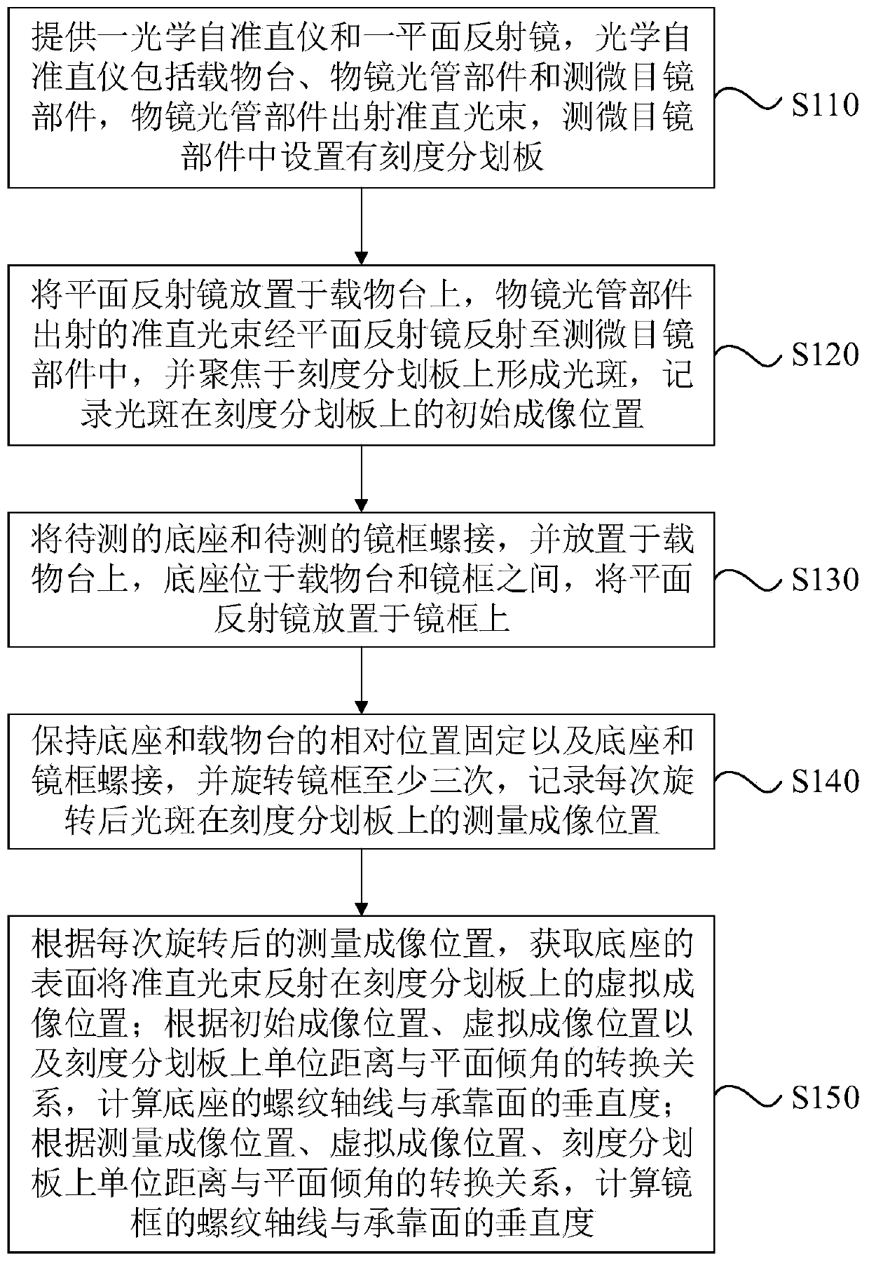
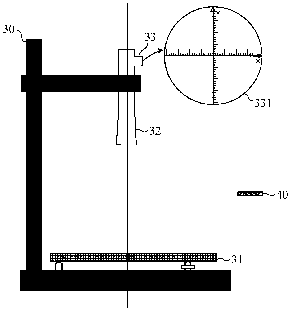
[0042] figure 1 It is a flow chart of a perpendicularity measurement method provided by an embodiment of the present invention, figure 2 It is a structural schematic diagram of a perpendicularity measuring device provided by an embodiment of the present invention, refer to figure 1 with figure 2 , the perpendicularity measurement method is used to measure the perpendicularity between the thread axis and the bearing surface in the base and frame, including:

[0043] S110, providing an optical autocollimator 30 a...


PUM

PropertyMeasurementUnit
Flatnessaaaaaaaaaa
Parallelismaaaaaaaaaa

Abstract

The embodiment of the invention discloses a perpendicularity measuring method and device. The perpendicularity measuring method comprises: providing an optical autocollimator and a plane mirror; arranging the plane mirror on an objective table, reflecting a collimated beam by the plane mirror to form a light spot, and recording an initial imaging position of the light spot; enabling a base and a mirror frame to be in a screw joint relationship, arranging the base and the mirror frame on the objective table, and arranging the plane mirror on the mirror frame; rotating the mirror frame at leastthree times and recording a measurement imaging position of the light spot after rotation each time; according to the measurement imaging positions, acquiring a virtual imaging position reflected by the surface of the base; and calculating the perpendicularity of the respective thread axes of the base and the mirror frame and a bearing surface according to the e initial imaging position, the measurement imaging positions, the virtual imaging position, and a conversion relationship between a unit distance and a plane inclination angle on a scale dividing plate. According to the invention, the perpendicularity of the respective thread axes of the base and the mirror frame and the bearing surface can be measured and calculated simultaneously, so that the measurement efficiency of the perpendicularity is improved; and the calculation accuracy of the perpendicularity is ensured.

Description

technical field [0001] Embodiments of the present invention relate to the technical field of optical instrument detection, and in particular to a method and device for measuring perpendicularity. Background technique [0002] Currently in the field of cameras, the lens is generally connected to the camera through a base, so that the imaging surface of the lens and the image sensor of the camera overlap. Specifically, the lens is composed of a frame and a lens installed in the frame. The frame and the base are respectively provided with external threads and internal threads. , to resist each other when screwing. Obviously, whether the axis of the thread is perpendicular to the bearing surface determines whether the final imaging surface of the lens in the frame is parallel or even coincides with the plane where the image sensor in the camera is located. [0003] With the improvement of the imaging quality of the lens and the increase of the aperture, the depth of focus of t...

Claims


Application Information

Patent Timeline
IPC IPC(8): G01B11/27
CPCG01B11/27
Inventor 张品光马育国米士隆王丹艺何剑炜
Owner DONGGUAN YUTONG OPTICAL TECH
Learn More