Aviation transient electromagnetic method receiving compensation device

A technology of transient electromagnetic method and compensation device, which is applied in measurement devices, electric/magnetic exploration, special electric/magnetic detection during transportation, etc. Compensation and overcompensation cannot obtain measurement signals, etc., to achieve the effects of improved detection depth and resolution, complete suppression, and convenient assembly.

Active Publication Date: 2019-10-22
INST OF GEOLOGY & GEOPHYSICS CHINESE ACAD OF SCI
View PDF16 Cites 7 Cited by
  • Summary
  • Abstract
  • Description
  • Claims
  • Application Information

AI Technical Summary

Problems solved by technology

[0004] The shortcoming of the existing airborne transient electromagnetic method receiving compensation method is that the transmitting compensation coil can greatly suppress the primary field induction signal, but since the position of the compensation coil is crucial to the compensation effect, in actual implementation, it is difficult to obtain and theoretical The effect of suppression, for example, the transmitting coil usually uses a polygon to approximate a circle, and the compensation coil is difficult to adjust to the ideal position, which leads to the problem of under-compensation or over-compensation of the receiving magnetic field. Under-compensation and over-compensation cannot obtain a truly ideal measurement signal; In addition, the launch compensation coil also weakens the energy injected into the earth by the primary field, reduces the intensity of the secondary field, and loses the ability to detect the effect

Method used


Image

  • Aviation transient electromagnetic method receiving compensation device
  • Aviation transient electromagnetic method receiving compensation device
  • Aviation transient electromagnetic method receiving compensation device

Examples


Embodiment Construction

[0023] In order to make the purpose, technical solution and advantages of the present application clearer, the present application will be further described in detail below in conjunction with the accompanying drawings and embodiments. It should be understood that the specific embodiments described here are only used to explain the present application, not to limit the present application.

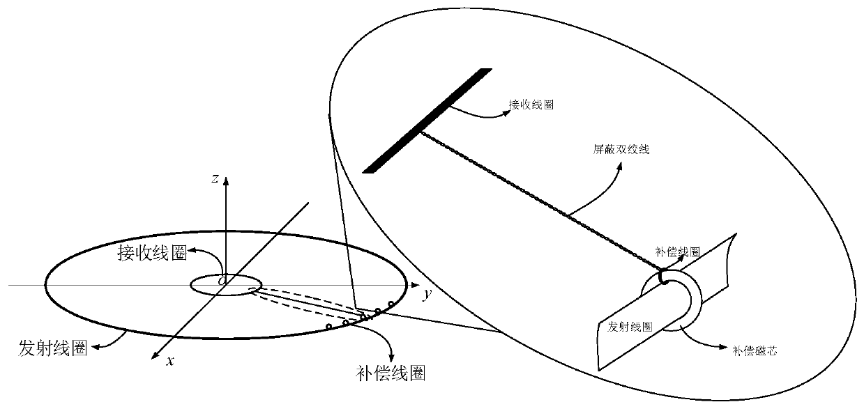
[0024] see image 3 , image 3 It is a structural schematic diagram of the receiving and compensating device for the aeronautical transient electromagnetic method of the embodiment of the present application. The receiving and compensating device for the aeronautical transient electromagnetic method of the embodiment of the present application includes a transmitting coil, a receiving coil, at least one compensating magnetic core and a plurality of compensating coils. Among them, the compensation magnetic core is a magnetic ring, the transmitting coil is arranged on the periphery of the ...


PUM


Abstract

The invention relates to an aviation transient electromagnetic method receiving compensation device. The aviation transient electromagnetic method receiving compensation device comprises a receiving coil, a transmitting coil, a compensation coil, and at least one compensating magnetic core. The transmitting coil is arranged at a periphery of the receiving coil, the compensating magnetic core is arranged on the transmitting coil, and the compensating coil is arranged on the compensating magnetic core. By using the aviation transient electromagnetic method receiving compensation device, throughadding compensation to the receiving coil, debugging is more flexible, assembling is more convenient, and suppression is more thorough. Besides, the proposed receiving and compensation coils do not weaken energy injected into the earth by a primary field, do not weaken a secondary field signal, and have no influence on a detection capability. Since full compensation of the primary field can be realized, a cleaner secondary field signal can be obtained. A detection depth and a resolution are greatly increased.

Description

technical field [0001] The application belongs to the technical field of polymetallic ore detection, and in particular relates to a receiving and compensating device for aerial transient electromagnetic method. Background technique [0002] The airborne transient electromagnetic method is a polymetallic ore detection method commonly used in the world in recent years. It has the advantages of fast speed, high efficiency, large exploration depth, high resolution, and small terrain influence. It is especially suitable for shallow coverage areas where work is difficult. [0003] The positional relationship between the transmitting coil and the receiving coil of the existing airborne transient electromagnetic method is as follows: figure 1 shown. The transceiver coil is on a horizontal plane, and its shape and position are usually close to two concentric circles. The transmitting coil has a radius of about 25 meters and has 3-6 turns, and the receiving coil has a radius of abou...

Claims


Application Information

Patent Timeline
Patent Type & Authority Applications(China)
IPC IPC(8): G01V3/10
CPCG01V3/107G01V3/16
Inventor 底青云真齐辉
Owner INST OF GEOLOGY & GEOPHYSICS CHINESE ACAD OF SCI
Why Eureka
Try Eureka