Time-constrained simultaneous-arrival multi-unmanned-aerial-vehicle path planning algorithm

A path planning and unmanned aerial vehicle technology, applied in the direction of vehicle position/route/height control, non-electric variable control, instruments, etc., can solve the problems that cannot be realized in terms of time, coordination, speed adjustment, upper and lower limits, etc.

Active Publication Date: 2019-10-22
NO 60 RES INST OF GENERAL STAFF DEPT PLA
View PDF11 Cites 11 Cited by
  • Summary
  • Abstract
  • Description
  • Claims
  • Application Information

AI Technical Summary

Problems solved by technology

Only path planning is used, usually equal-length paths are designed, and the speed of each point of the UAV is determined. When the speed drops and the speed control deviation is large, the coordination in time cannot be achieved; for the speed coordination control, the disadvantage is that there are upper and lower restrictions on the speed adjustment. , so there is no good solution for multi-UAV cooperative flight at present, it is necessary to provide a new path planning method to meet the actual needs of multi-UAV fleet cooperative flight

Method used

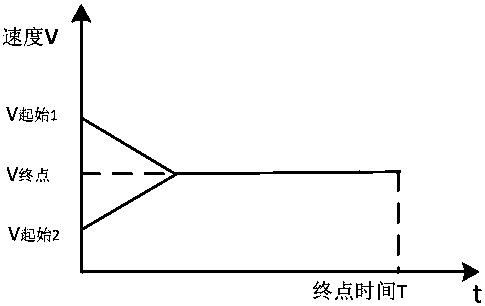
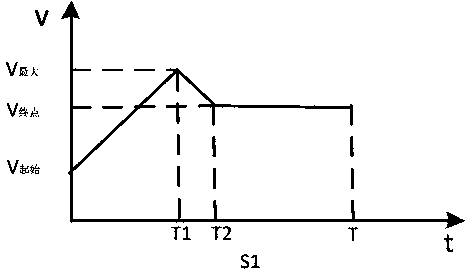
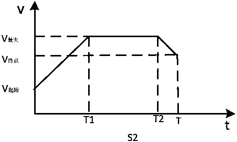

Image

  • Time-constrained simultaneous-arrival multi-unmanned-aerial-vehicle path planning algorithm
  • Time-constrained simultaneous-arrival multi-unmanned-aerial-vehicle path planning algorithm
  • Time-constrained simultaneous-arrival multi-unmanned-aerial-vehicle path planning algorithm

Examples


Embodiment 1

[0050] In a two-dimensional plane, 5 aircrafts in different positions have limited starting / ending speeds, starting / ending headings, turning radius, and flight time. The initial simulation parameters are shown in the table below.

[0051] Table 1 Initial simulation parameters of multiple UAVs

[0052] flight duration starting speed terminal speed starting point X starting point Y Minimum turning radius initial heading End point X end point Y Minimum turning radius End heading aircraft 1 900 140 160 100 100 5000 90 50000 70000 5000 140 aircraft 2 900 140 160 20000 150000 5000 0 50100 70200 5000 140 aircraft 3 900 140 160 60000 200000 5000 0 50000 70100 5000 140 aircraft 4 900 140 160 100000 200000 5000 0 50200 70200 5000 140 aircraft 5 900 140 160 120000 0 5000 270 50000 70200 5000 140

[0053] The maximum flight speed is 270m / s; the maximum acceleration and deceler...

Embodiment 2

[0055] In three-dimensional space, 3 aircrafts in different positions have limited starting / ending speeds, starting / ending headings, turning radius, and flight time. The initial simulation parameters are as follows.

[0056] Table 2 Initial simulation parameters of multiple UAVs

[0057] starting point X starting point Y Starting point Z Minimum turning radius starting heading starting speed aircraft 1 2622 26843 1475 4000 9 140 aircraft 2 1497 6694 8713 4000 87 160 aircraft 3 12416 23715 9935 4000 241 200 End point X end point Y End Z Minimum turning radius End heading terminal speed aircraft 1 12159 30149 9776 4000 230 180 aircraft 2 4684 13461 1724 4000 204 180 aircraft 3 27726 26201 1677 4000 252 180

[0058] The maximum flight speed is 270m / s; the maximum acceleration and deceleration capability is 0.5m / s 2 ; The maximum rate of climb is 3m / s; the flight time is 1...


PUM


Abstract

The invention relates to a path planning method for an unmanned aerial vehicle group, particularly to a time-constrained simultaneous-arrival multi-unmanned-fixed-wing-aircraft planning path planningalgorithm, thereby realizing coordinated flight of the unmanned aerial vehicle group having specific time requirements of same-time arrival and successive-time interval arrival. The invention providesa time-constrained simultaneous-arrival multi-unmanned-aerial-vehicle path planning algorithm. A three-dimensional reference path length is planned by considering the speed, acceleration and deceleration limits of an unmanned aerial vehicle under the flight time requirement; three-dimensional path information is determined by radius searching within an available path length range; and then a current speed given value and a speed adjusting value are calculated based on flight time to carry out real-time speed controlling. Therefore, the coordinated flight time requirements of multiple UAVs aremet.

Description

technical field [0001] The present invention relates to a time-constrained simultaneous arrival path planning algorithm for multiple unmanned fixed-wing aircraft, which relates to a path planning method for UAV fleets, which can realize simultaneous arrival of UAV fleets and arrival at successive time intervals within time intervals. Coordinated flight for specific requirements. Background technique [0002] Time Constraint Simultaneous arrival of multiple unmanned fixed-wing aircraft The path planning algorithm will require multiple UAVs to arrive at the target point at the same time. For the problem of simultaneous arrival, the strategy of path planning and speed cooperative control is usually used to complete. Only path planning is used, and equal-length paths are usually designed. The speed of each point of the UAV is determined. When the speed drops and the speed control deviation is large, it is impossible to achieve time coordination. For speed cooperative control, th...

Claims


Application Information

Patent Timeline
Patent Type & Authority Applications(China)
IPC IPC(8): G05D1/10
CPCG05D1/104
Inventor 张振兴宋少杰刘俊雲
Owner NO 60 RES INST OF GENERAL STAFF DEPT PLA
Why Eureka
Try Eureka