
A method and device for improving the utilization rate of DDR storage bus

A storage bus, utilization technology, applied in the field of data communication, can solve problems such as inability to adjust, waste of bandwidth and bus resources, etc.

Inactive Publication Date: 2020-11-10
南京凯鼎电子科技有限公司
View PDF10 Cites 0 Cited by
  • Summary
  • Abstract
  • Description
  • Claims
  • Application Information

AI Technical Summary

Problems solved by technology

[0004] In the existing technology, the DDR controller only checks whether the commands in the cached command queue have the same bank and the same row, and adjusts the commands of the same bank and the same row so that the commands of the same bank and row Continuous transmission, but such adjustment has the following disadvantages: the adjustment is only valid for commands that have been buffered in the command queue, and usually, the queue depth of the command queue is too small, because the power consumption and area of ​​the chip need to be considered at the same time. The general Buffer (cache) depth will be 8-16, and many commands may be the same bank and row after the 16th, so the existing technology can always only solve the Buffer depth within the range of 16 commands , the depth over 16 cannot be adjusted
As a result, the commands of the same bank and the same row are separated. When the separated running time is greater than the closing time of the bank, when the row of the bank is addressed again, the bank and row need to be activated again, then it will Repeated waste of bandwidth and bus resources

Method used


Image

  • A method and device for improving the utilization rate of DDR storage bus
  • A method and device for improving the utilization rate of DDR storage bus

Examples


Embodiment Construction

[0025] It should be understood that the specific implementation manners described here are only used to explain the present invention, but not to limit the present invention.

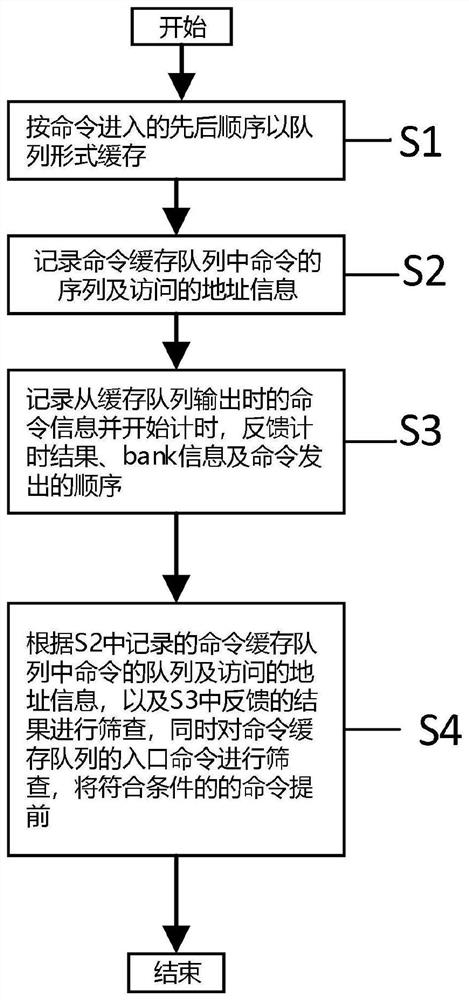
[0026] figure 1 A flow chart of a method for improving storage bus utilization in an embodiment of the present invention is shown, and the process includes the following steps:

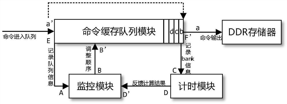
[0027] Step S1, receiving commands, and buffering them according to the order of command entries to form a command buffer queue, and outputting the commands to the DDR memory. In an embodiment, the command buffer queue can be buffered in the command buffer queue module.

[0028] Step S2, while forming the command buffer queue, record the sequence of the commands in the command buffer queue and the address information of the access. In an embodiment, the monitoring module can be used to record the command information in the command buffer queue. When a command is entered into the command cache queue module, the monitoring mod...


PUM


Abstract

The invention provides a method for improving the utilization rate of DDR storage bus, comprising the following steps: (1) accepting commands, buffering according to the order of command entries to form a command buffer queue, and outputting commands to the DDR memory; (2) forming the command buffer While in the queue, record the sequence of commands in the command cache queue and the address information of the visit; (3) record the command address information when output from the command cache queue and start timing, feedback timing results, bank information; (4) according to step (2 ) in the command cache queue recorded in ) and the address information accessed, as well as the results fed back in step (3), are screened to find commands of the same bank and same row, and advance the commands of the same bank and same row to the front of the command cache queue . The invention also provides a device for improving the utilization rate of the DDR storage bus, which is composed of a command buffer queue module, a timing module and a monitoring module. A method or device for improving the utilization rate of the DDR storage bus provided by the present invention can be completely limited by t RAS Time is the standard, and the sending order can be adjusted for the DDR controller command cache queue and the commands of the same bank and the same row near the entrance and exit, thereby improving the utilization rate of the DDR storage bus.

Description

technical field [0001] The invention relates to the technical field of data communication, in particular to a method and a device for improving the utilization rate of a DDR storage bus. Background technique [0002] In DDR (dual-channel dynamic random access memory), an active (activation) operation is first performed on a row (such as bankArowB) of a bank (storage body), and then the bankArowB will remain in the active state for a period of time until it is closed. This time period is called t RAS (line command activates gap). at t RAS After the (line command activation gap) time, the system will close the bankArowB, that is, the charging operation of PRECHARGE (charging). After that, if you want to activate bankArowB or other rows of bankA, you need to wait for t RP (minimum delay interval from PRECHARGE to the next active operation) before it can be activated again. [0003] In a general DDR controller, there will be a certain amount of Buffer (cache) depth to store...

Claims


Application Information

Patent Timeline
Patent Type & Authority Patents(China)
IPC IPC(8): G06F13/16G06F3/06
CPCG06F3/0656G06F3/0658G06F3/0659G06F13/1673
Inventor 宋超黄年畤
Owner 南京凯鼎电子科技有限公司
Learn More