
Storage battery and voltage stabilizing source switching power supply circuit applied to cubesat

A technology of power supply circuit and battery, applied in the field of CubeSats, can solve the problems of being unsuitable for the high functional density of CubeSats, limiting the continuity of the debugging process, increasing the number of battery cycles, etc., to achieve ingenious design, low energy loss, and high design reliability. Effect

Active Publication Date: 2019-10-22
NANJING UNIV OF SCI & TECH
View PDF5 Cites 2 Cited by
  • Summary
  • Abstract
  • Description
  • Claims
  • Application Information

AI Technical Summary

Problems solved by technology

At this time, we can only stop the debugging and charge the battery, which greatly limits the continuity of the debugging process; or use a stabilized voltage source to debug while charging the battery, which increases the cycle times of the battery and damages the life of the battery.
[0004] In order to solve this problem, the existing large satellites will add a relay between the battery and the busbar, and manually disconnect the connection between the battery and the busbar during ground debugging, but the relay is often bulky and not suitable for the high functional density of the cubesat; In addition, the iron core in the relay coil will generate residual magnetism, which will interfere with the original magnetic field in space and affect the attitude control of the satellite; the operation of disconnecting the battery from the bus needs to be done manually, and cannot be switched automatically

Method used


Image

  • Storage battery and voltage stabilizing source switching power supply circuit applied to cubesat

Examples


Embodiment Construction

[0030] The present invention will be described in detail below in conjunction with the accompanying drawings and specific embodiments.

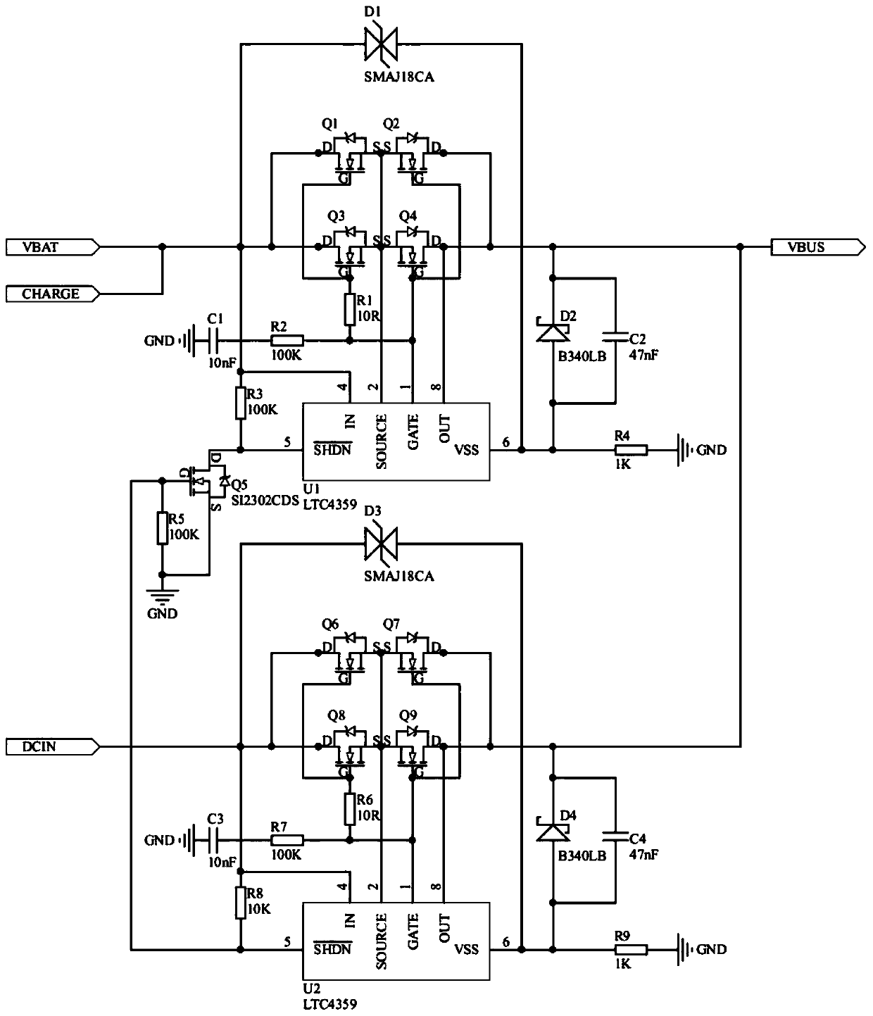
[0031] combine figure 1 , a switching power supply circuit for a storage battery and a regulated source applied to a cube star, comprising a battery power supply circuit and a regulated source power supply circuit, the front end of the battery power supply circuit is connected to a battery module on the star, and the front end of the regulated voltage source power supply circuit is connected For the off-planet stabilized voltage source equipment, the rear ends of the battery power supply circuit and the stabilized voltage source power supply circuit are connected to the bus bar of the on-star power supply system.

[0032] The battery power supply circuit includes a first integrated chip U1 (LTC4359), a first resistor R1 (10R), a second resistor R2 (100K), a third resistor R3 (100K), a fourth resistor R4 (1K), and a fifth resistor R5 (100K), ...


PUM

PropertyMeasurementUnit
Fifth resistoraaaaaaaaaa
Eighth resistoraaaaaaaaaa

Abstract

The invention discloses a storage battery and voltage stabilizing source switching power supply circuit applied to a cubesat. The circuit comprises a storage battery power supply circuit and a voltagestabilizing source power supply circuit; the front end of the storage battery power supply circuit is connected with a storage battery module on a satellite; the front end of the voltage stabilizingsource power supply circuit is connected with a voltage stabilizing source device outside the satellite; and the rear ends of the storage battery power supply circuit and the voltage stabilizing source power supply circuit are connected with a bus of an on-satellite power supply system. After the voltage stabilizing source power supply circuit is connected with the voltage stabilizing source device outside the satellite, the voltage stabilizing source power supply circuit connects a voltage stabilizing source with the bus, the storage battery power supply circuit disconnects a storage batteryfrom the bus, the voltage stabilizing source provides power consumption during debugging of the whole satellite, and electric energy in the storage battery is not used. When the voltage stabilizing source power supply circuit is not connected with the voltage stabilizing source device, the storage battery power supply circuit connects the storage battery with the bus, and the storage battery provides power consumption for the whole satellite during working. The power supply can be automatically switched, the use is convenient, the thought is novel, and the problem of insufficient power storageof the storage battery during long-time debugging of the cubesat is solved.

Description

technical field [0001] The invention relates to the technical field of cube stars, in particular to a switching power supply circuit applied to a storage battery and a voltage stabilizing source of a cube star. Background technique [0002] In recent years, with the rapid development of communication, optoelectronic components, materials, sensors, and other technologies, cube satellites with low cost and high functional density have gradually emerged, which greatly reduces the development cost and development cycle of satellites. Remote measurement and testing become possible. [0003] As an important subsystem of CubeSat, the power supply system is to ensure safe and reliable power supply for the whole star during in-orbit flight and long-term stable power supply for the whole star during ground debugging. Since the various high-power loads on the star only work for a short time per orbit during orbital flight, the battery of the power system is sufficient for the power co...

Claims


Application Information

Patent Timeline
IPC IPC(8): H02J9/06
CPCH02J9/061
Inventor 张翔从伟晨梁振华
Owner NANJING UNIV OF SCI & TECH
Learn More