Vibration type sand screening device convenient to clean
A vibrating sand screening technology, which is applied in the direction of heating device, filter screen, solid separation, etc., can solve the time-consuming and labor-intensive problems, and achieve the effect of improving screening efficiency, reducing moisture content, and fast impurity removal
- Summary
- Abstract
- Description
- Claims
- Application Information
AI Technical Summary
Problems solved by technology
Method used
Image
Examples
Embodiment 1
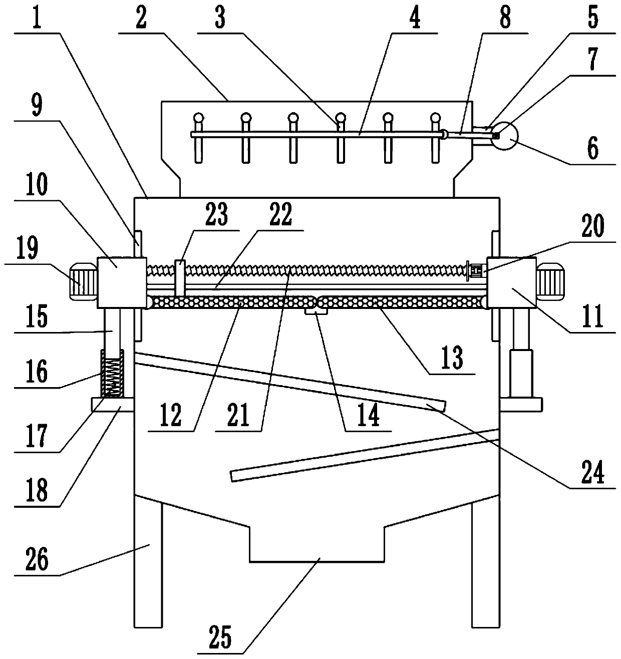
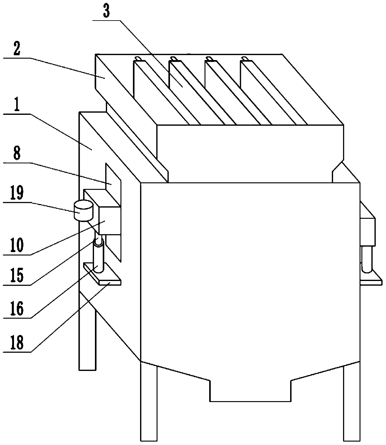
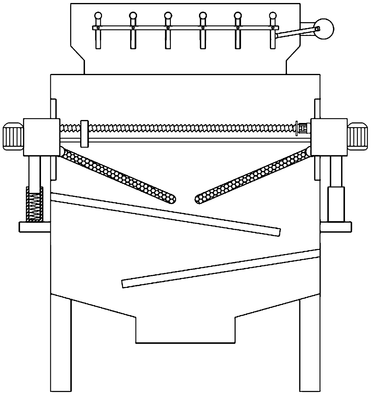
[0023] see Figure 1-3 , in an embodiment of the present invention, a vibrating sand screening device that is easy to clean includes a housing 1, a feeding port 2, a left slider 10, a right slider 11, a left sieve plate 12 and a right sieve plate 13, and the top of the housing 1 The feeding port 2 is fixedly connected, the left side wall and the right side wall of the casing 1 are respectively provided with chute 9, the left and right sides of the casing 1 are symmetrically provided with a left slider 10, a right slider 11, a left slider 10, a right slider The blocks 11 are respectively embedded in the chute 9, the left slider 10 and the right slider 11 can slide up and down, the left slider 10 is hinged with a left sieve plate 12, the right slider 11 is hinged with a right sieve plate 13, and a left sieve plate 12 , right sieve plate 13 is arranged symmetrically, the middle part of left sieve plate 12 and right sieve plate 13 is connected by movable buckle 14, sand falls on l...
Embodiment 2
[0025] see Figure 4 , on the basis of Embodiment 1, a material distribution mechanism is installed in the feeding port 2, and the material distribution mechanism includes a material distribution partition 3, a first connecting rod 4, a material distribution motor 5, a turntable 6, a fixed rod 7 and a second connecting rod. Rod 8, the inside of feeding opening 2 is equipped with some material dividing partitions 3, the upper end of feeding dividing dividing plate 3 is connected with the inner wall of feeding opening 2 in rotation, the middle part of material dividing dividing plate 3 is penetrated with first connecting rod 4, the first The connecting rod 4 is hinged with the material distribution partition 3, the outer wall of the feeding port 2 is fixedly connected with a material distribution motor 5, the shaft extension end of the material distribution motor 5 is provided with a turntable 6, and the surface of the turntable 6 is fixedly connected with a fixed Rod 7, the sec...
Embodiment 1、 Embodiment 2
[0026] Combined with Embodiment 1 and Embodiment 2, the working principle of the present invention is: put the sand to be screened into the feeding port 2, start the material distribution motor 5, drive the turntable 6 to rotate, and then drive the first connecting rod 4 through the second connecting rod 8 Move left and right, thereby driving the material distribution partition 3 to swing left and right, the sand to be screened is put into the feeding port 2, and the material distribution partition 3 swings left and right, so that the sand is dispersed and evenly falls into the shell 1, which is helpful for the sand screening operation. Carry out, sand falls on left sieve plate 12, right sieve plate 13, utilize left sieve plate 12, right sieve plate 13 to screen sand, start vibration motor 19, under the cooperation of spring 17, left slider 10, right slide The block 11 vibrates up and down, thereby driving the left sieve plate 12 and the right sieve plate 13 to vibrate up and d...
PUM
 Abstract
Description
Claims
Application Information
 - R&D
- Intellectual Property
- Life Sciences
- Materials
- Tech Scout
- Unparalleled Data Quality
- Higher Quality Content
- 60% Fewer Hallucinations
Browse by: Latest US Patents, China's latest patents, Technical Efficacy Thesaurus, Application Domain, Technology Topic, Popular Technical Reports.
© 2025 PatSnap. All rights reserved.Legal|Privacy policy|Modern Slavery Act Transparency Statement|Sitemap|About US| Contact US: help@patsnap.com


