Machining-stable steel structure cutting device

A cutting device and steel structure technology, applied in positioning devices, metal processing equipment, metal processing machinery parts, etc., can solve problems such as unstoppable splashing iron filings and dust, affecting the processing quality of steel structures, and endangering the health of workers, etc. To achieve the effect of improving clamping effect, improving cutting effect and improving cutting quality

Inactive Publication Date: 2019-10-25
重庆宝高实业有限公司
7 Cites 6 Cited by

AI-Extracted Technical Summary

Problems solved by technology

[0005] Aiming at the deficiencies of the prior art, the present invention provides a steel structure cutting device with stable processing, which solves the problem that the equipment in the reference document cannot block the splashed ...

Method used

Wherein, the inside of support base 1 is provided with the water storage rectangular groove 16 that is communicated with cutting groove 15, and the inner wall bottom of water storage rectangular groove 16 is equipped with the circulating water pump 17 that is electrically connected with controller, the model of circulating water pump 17 It is WQD, the working voltage is 220V, the water outlet end of the circulating water pump 17 is connected with the water guide pipe 18, and the end of the water guide pipe 18 extends to the top of the support base 1 and is inserted into the inside of the isolation case 12, and the circulating water pump 17 stores water in a rectangular shape. The water in the groove 16 is discharged to the side wall of the cutting piece 6 through the water guide pipe 18, which can cool down the rotating cutting piece 6, avoiding the impact of high temperature on the cutting piece 6 and the steel structure cutting place, and helping to improve the cutting quality. The service life of the cutting blade 6 is prolonged, which is beneficial to save processing costs, and the cooled water enters the inside of the rectangular water storage tank 16 through the cutting tank 15, and can be recycled to save water resources.
Wherein, the inside of the water storage rectangular tank 16 and the outer wall of the support base 1 are all...

Abstract

The invention provides a machining-stable steel structure cutting device, and relates to the technical field of steel structure machining. The machining-stable steel structure cutting device comprisesa support base; the top of the support base is connected with an electric push rod; the top of the electric push rod is connected with a support plate; a suspended frame box is mounted in the bottomcenter of the support plate; a driving motor is bolted to the bottom of the inner wall of the suspended frame box; and a cutting blade is welded on an output shaft of the driving motor. In the machining-stable steel structure cutting device, when the cutting blade is descended for cutting, steel structures can be fixedly clamped by lateral clamping blocks, and the clamping effect is improved by springs, so that the cutting effect of the steel structures is improved, and the influence on the cutting quality by shaking in the cutting process is prevented; meanwhile, no manual operation is neededin the clamping operation, so that the operation is more convenient; and the cutting places can be cooled in the cutting process, so that the influence on the cutting blade and the cutting places ofthe steel structures by high temperature is prevented, and the cutting quality is improved.

Application Domain

Technology Topic

Image

  • Machining-stable steel structure cutting device
  • Machining-stable steel structure cutting device
  • Machining-stable steel structure cutting device

Examples

  • Experimental program(1)

Example Embodiment

[0027] The technical solutions in the embodiments of the present invention will be clearly and completely described below in conjunction with the accompanying drawings in the embodiments of the present invention. Obviously, the described embodiments are only a part of the embodiments of the present invention, rather than all the embodiments. Based on the embodiments of the present invention, all other embodiments obtained by those of ordinary skill in the art without creative work shall fall within the protection scope of the present invention.
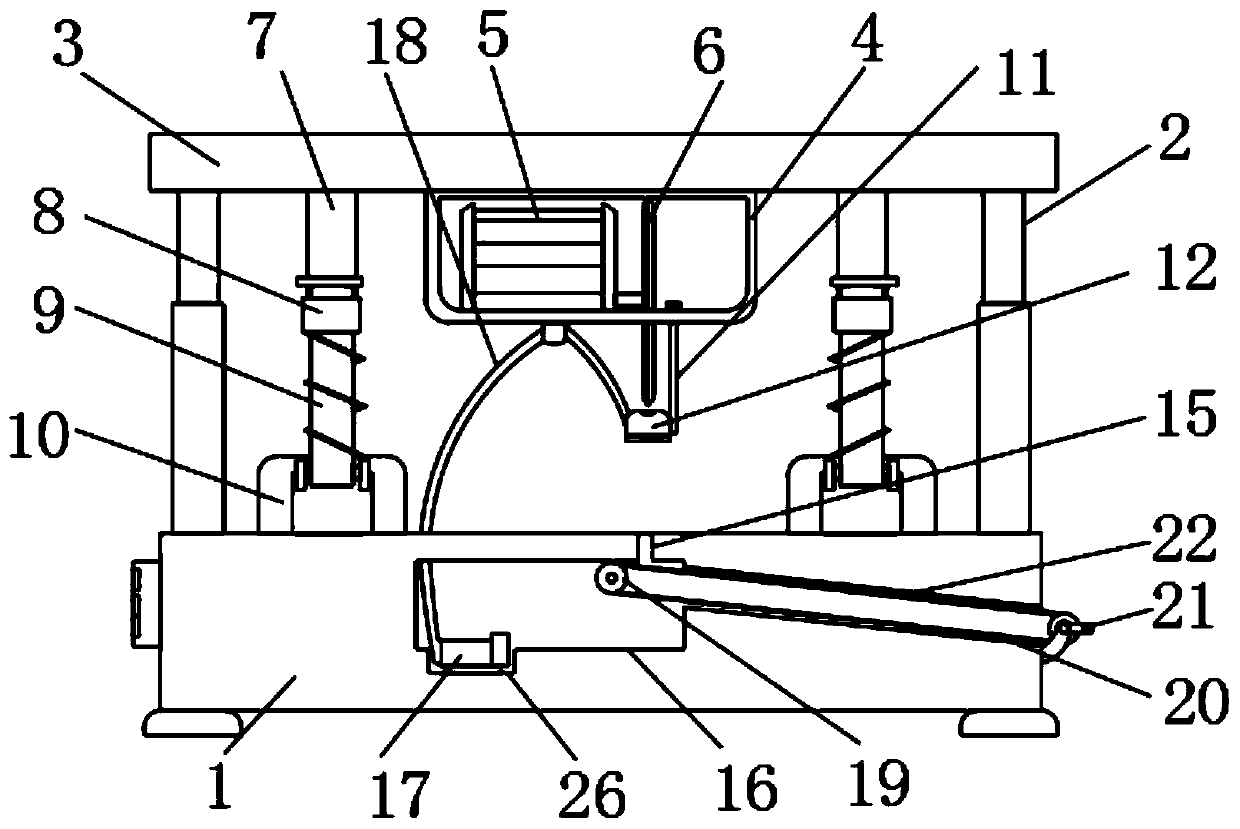
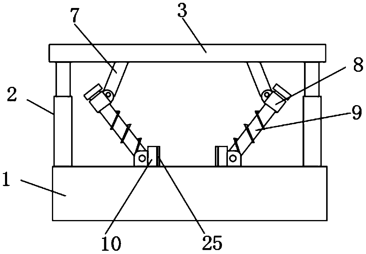
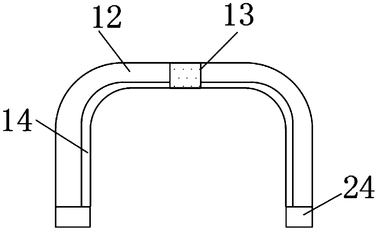
[0028] The embodiment of the present invention provides a steel structure cutting device with stable processing, such as Figure 1-4 As shown, the support base 1 is included. The top of the support base 1 is connected with an electric push rod 2, the top of the electric push rod 2 is connected with a support plate 3, and the bottom center of the support plate 3 is installed with a suspension box 4 and a suspension box 4 A drive motor 5 is bolted to the bottom of the inner wall, and the output shaft of the drive motor 5 is welded with a cutting blade 6. The model of the drive motor 5 is YDF-Z402-4, the power is 4KW, the rated torque is 3600N.M, and the support base 1 A controller electrically connected to the drive motor 5 and the electric push rod 2 is installed on the side wall. The model of the controller is CPU226, the rated power is 11w, the working voltage is 24V, and the bottom of the cutting blade 6 extends below the suspended frame box 4. Two sets of relatively inclined top pressing rods 7 are installed at the bottom of the support plate 3 and on the side of the suspended frame box 4. The bottom end of the top pressing rod 7 is hinged with a sleeve 8, and the inside of the sleeve 8 is inserted A slidable force applying rod 9 is connected, and the top pressing rod 7, sleeve 8 and force applying rod 9 are connected as follows figure 2 As shown, the bottom end of the force application rod 9 is hinged with a lateral clamp block 10 that is slidably connected to the support base 1, and the outer wall of the force application rod 9 is sleeved with a spring, and the steel structure to be cut is placed in the suspension box 4 When the electric push rod 2 shrinks and drives the support plate 3 to fall, the top pressure rod 7 drops and presses the force push rod 9 to make the bottom of the two force push rods 9 The ends move towards each other against the steel structure, the sleeve 8 can be lowered while compressing the spring, so that the biasing rod 9 always has a tendency to press the steel structure, firmly fix the steel structure, help improve the cutting quality, and drive the motor 5 Drive the high-speed rotating cutting blade 6 to cut the steel structure.
[0029] Among them, the bottom of the suspended frame box 4 is inserted with a retractable lifting rod 11, the bottom of the lifting rod 11 is connected with an isolation cover 12, and the isolation cover 12 is located directly below the cutting sheet 6, and the top of the isolation cover 12 is opened There is a strip through slot 13 that is compatible with the cutting sheet 6, and the inner wall of the isolation cover 12 is bonded with a sound-absorbing board 14, which is made of aluminum foil glass wool. The sound absorption and shock absorption are tested and the sound absorption effect is excellent, and the sound absorption coefficient It is a sound-absorbing, noise-reducing and shock-absorbing material with a low thermal conductivity and excellent thermal insulation effect. It supports the top of the base 1 and is located directly under the insulation cover 12, and is equipped with a cutting sheet 6 suitable for cutting Slot 15, the cutting piece 6 enters the interior of the isolation cover 12 before the cutting piece 6 contacts the steel structure. The isolation cover 12 covers the contact between the cutting piece 6 and the steel structure, and the noise generated by cutting can be isolated by the sound-absorbing board 14, which is effective This reduces the working noise and helps to improve the comfort of the staff. At the same time, the isolation cover 12 also shields the sparks and dust generated during cutting, which is beneficial to reduce the harm of cutting dust to the staff.
[0030] The inside of the support base 1 is provided with a rectangular water storage tank 16 communicating with the cutting tank 15. A circulating water pump 17 electrically connected to the controller is installed at the bottom of the inner wall of the rectangular water storage tank 16. The model of the circulating water pump 17 is WQD, The working voltage is 220V. The water outlet end of the circulating water pump 17 is connected with a water pipe 18, and the end of the water pipe 18 extends above the support base 1 and is inserted into the interior of the isolation cover 12. The circulating water pump 17 stores the water in the rectangular tank 16 The water is discharged to the side wall of the cutting blade 6 through the water pipe 18, which can cool the rotating cutting blade 6, avoiding high temperature from affecting the cutting blade 6 and the cutting part of the steel structure, which helps to improve the cutting quality and extend the cutting The service life of the sheet 6 is conducive to saving processing costs. The cooled water enters the inside of the water storage rectangular tank 16 through the cutting groove 15 and can be recycled and can save water resources.
[0031] The inside of the rectangular water storage tank 16 and the outer wall of the support base 1 are both movably connected with a rotating drum 19, and the outer walls of the two rotating drums 19 are sleeved with a filter 20. The filter 20 is an elliptical shape connected at both ends. 20 is located below the cutting groove 15, the end of the filter screen 20 located outside the support base 1 is lower than the end located inside the rectangular water storage tank 16, and the support base 1 is provided with a chute 22 adapted to the filter screen 20. The cooling water level inside the rectangular water storage tank 16 is lower than that of the chute 22, and the cooling water falls on the filter screen 20 through the cutting groove 15, which can intercept iron filings and other debris in the water, which is beneficial to the stable circulation of the cooling water. Rotate the rotating drum 19 The oval-shaped filter screen 20 can be rotated, and the iron filings on the filter screen 20 can be discharged, and the cleaning operation is simple and convenient.
[0032] Wherein, the side wall of the rotating drum 19 supporting the outer wall of the base 1 is equipped with a control handle 21, and the control handle 21 is right-angled to facilitate the rotation of the rotating drum 19.
[0033] Wherein, the top of the support base 1 is provided with an anti-leakage roof groove 23, and the cutting groove 15 is located at the center of the anti-leakage roof groove 23 to facilitate the cooling water to enter the inside of the cutting groove 15.
[0034] Among them, a rubber strip 24 is adhered to the bottom of the insulation cover 12, and the rubber strip 24 is frame-shaped, which improves the sealing effect of the insulation cover 12 on the cut of the steel structure.
[0035] Wherein, the side wall of the lateral clamping block 10 is bonded with a contact rubber plate 25, and the side of the contact rubber plate 25 away from the lateral clamping block 10 is provided with a rough surface, which improves the clamping effect of the lateral clamping block 10 on the steel structure .
[0036] Among them, a water storage tank 26 is opened on the bottom side of the inner wall of the rectangular water storage tank 16, and the water storage tank 26 is matched with the circulating water pump 17 to facilitate the pumping of the circulating water pump 17.
[0037] Working principle: When in use, place the steel structure to be cut under the suspension box 4 and between the two sets of lateral clamping blocks 10. When the electric push rod 2 shrinks and drives the support plate 3 to fall, the top pressure rod 7 drops Press down on the force lever 9 to make the bottom ends of the two force levers 9 move toward each other to resist the steel structure. The sleeve 8 can be lowered while compressing the spring, so that the force lever 9 always has a tendency to exert pressure on the steel structure , The steel structure is firmly fixed, and the high-speed rotating cutting blade 6 is driven by the drive motor 5 to cut the steel structure. The cutting blade 6 enters the interior of the isolation housing 12 before it contacts the steel structure, and the isolation housing 12 will cut The contact between the sheet 6 and the steel structure is covered, and the noise generated by cutting can be isolated by the sound-absorbing board 14. At the same time, the isolation cover 12 also shields the sparks and dust generated during cutting. The circulating water pump 17 places the water in the rectangular groove 16 The water is discharged to the side wall of the cutting blade 6 through the water pipe 18, which can cool the rotating cutting blade 6 to avoid high temperature from affecting the cutting blade 6 and the steel structure cutting. The cooled water enters the water storage through the cutting groove 15 The inside of the rectangular groove 16 can be recycled. The cooling water falls on the filter screen 20 through the cutting groove 15 to intercept iron filings and other debris in the water, which is conducive to the stable circulation of the cooling water. Rotating the rotating drum 19 can make the oval shape The filter screen 20 rotates to discharge iron filings on the filter screen 20.
[0038] It should be noted that in this article, relational terms such as first and second are only used to distinguish one entity or operation from another entity or operation, and do not necessarily require or imply one of these entities or operations. There is any such actual relationship or order between. Moreover, the terms "include", "include" or any other variants thereof are intended to cover non-exclusive inclusion, so that a process, method, article or device including a series of elements not only includes those elements, but also includes those that are not explicitly listed Other elements of, or also include elements inherent to this process, method, article or equipment.
[0039] Although the embodiments of the present invention have been shown and described, those of ordinary skill in the art can understand that various changes, modifications, and substitutions can be made to these embodiments without departing from the principle and spirit of the present invention. And variations, the scope of the present invention is defined by the appended claims and their equivalents.

PUM

no PUM

Description & Claims & Application Information

We can also present the details of the Description, Claims and Application information to help users get a comprehensive understanding of the technical details of the patent, such as background art, summary of invention, brief description of drawings, description of embodiments, and other original content. On the other hand, users can also determine the specific scope of protection of the technology through the list of claims; as well as understand the changes in the life cycle of the technology with the presentation of the patent timeline. Login to view more.

Similar technology patents

Novel clamping tool

Owner:天津市叁盛缘电子有限公司

Measuring equipment for balance coefficient of elevator

PendingCN111056398AGuaranteed clamping effectImprove clamping effectElevatorsMeasuring equipmentStress sensors
Owner:河南省特种设备安全检测研究院

Classification and recommendation of technical efficacy words

  • Improve cutting effect
  • Improve clamping effect

Paper towel cutting mechanism

ActiveCN105996880AImprove cutting effectDomestic applicationsPaper towel
Owner:杭州迅行物联网科技有限公司

Plant trimming apparatus and methods

ActiveUS20190124851A1Improve cutting effectEasy to disassembleBud removersMowersAngular rangeLanding zone
Owner:ETEROS TECH INC

Clamping assembly for milling machine

Owner:天津顺鑫福泰机械加工有限公司

Adjusting device for workpiece clamping

Owner:ANQING WEIZHIZHU ELECTRICAL APPLIANCE CO LTD
Why Eureka
Try Eureka