Device for deburring teeth of bevel gear

A burr removal and bevel gear technology, applied in the direction of gear teeth, belts/chains/gears, components with teeth, etc., can solve problems such as low efficiency, and achieve the effect of improving efficiency

Inactive Publication Date: 2019-10-25
付志青
View PDF7 Cites 5 Cited by
  • Summary
  • Abstract
  • Description
  • Claims
  • Application Information

AI Technical Summary

Problems solved by technology

[0007] The technical problem to be solved by the present invention is to provide a bevel gear tooth burr removal device for the current problem of low efficiency when manually removing burrs from bevel gears

Method used


Image

  • Device for deburring teeth of bevel gear
  • Device for deburring teeth of bevel gear

Examples


Embodiment Construction

[0023] The technical solutions in the embodiments of the present invention will be clearly and completely described below in conjunction with the drawings in the present invention. Apparently, the described embodiments are only some of the embodiments of the present invention, not all of them. Based on the embodiments of the present invention, all other embodiments obtained by persons of ordinary skill in the art without making creative efforts belong to the protection scope of the present invention. If the words "up", "down", "left" and "right" appear in the following, it only means that they are consistent with the directions of up, down, left and right in the drawings themselves, and do not limit the structure.

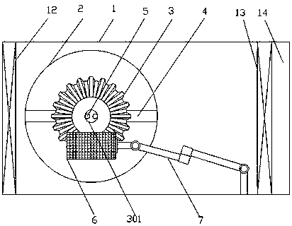
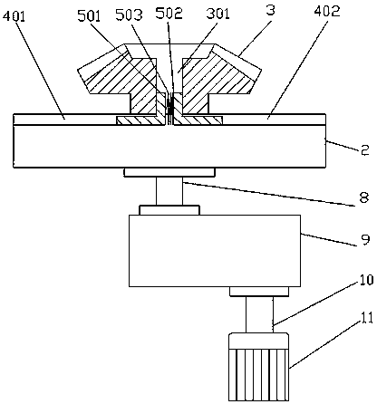
[0024] Such as figure 1 and figure 2 A bevel gear tooth deburring device shown includes a bevel gear 3, a gear center hole 301, a body 1, an electric brush 6, a motor 11, a reducer 9 and a universal adjustment bracket 7; the upper end of the body 1 is provided wi...


PUM


Abstract

The invention discloses a device for deburring teeth of a bevel gear, and belongs to the field of machining equipment. Main technical points in the invention are as follows: the teeth of the bevel gear are deburred by rotation of an electric hairbrush fixed on a universal adjustment frame; the bevel gear is fixed on a turntable in the device through a fixing assembly; the turntable drives the bevel gear to rotate slowly; and thus, teeth around the bevel gear are completely deburred by the electric hairbrush. Each tooth does not need to be artificially polished one by one; therefore, the productivity is saved; and the structure is simple.

Description

technical field [0001] The invention belongs to the field of mechanical processing equipment, and in particular relates to a bevel gear tooth burr removal device. Background technique [0002] Bevel gears are bevel gears, bevel gears. Bevel gears are most commonly used for transmission of two vertical shafts, but are also suitable for transmission of two shafts at other angles. The most typical application is to drive a vertical pump with a horizontal drive. The two main differences between bevel and spur gears are their shape and their relationship to the shafts on which they sit. Bevel gears are conical in shape while spur gears are originally a cylinder. Bevel gears transmit motion between two angled axes, or crossed axes, while spur gears transmit motion between two parallel axes. [0003] Burrs are irregular parts such as various sharp edges and burrs that appear on the surface of workpieces during the manufacturing process of metals and non-metals. Burrs will affec...

Claims


Application Information

Patent Timeline
Patent Type & Authority Applications(China)
IPC IPC(8): B23F19/00
CPCB23F19/00
Inventor 付志青
Owner 付志青
Why Eureka
Try Eureka