Bidirectional powder pavement device used for 3D printing process

A powder spreading device and 3D printing technology, which is applied in the field of 3D printing, can solve the problems of powder agglomeration without feeding, powder output and powder compactness uncontrollable, etc., and achieve the effect of avoiding powder agglomeration

Active Publication Date: 2019-10-25
山东汇景信息科技有限公司
View PDF9 Cites 6 Cited by
  • Summary
  • Abstract
  • Description
  • Claims
  • Application Information

AI Technical Summary

Problems solved by technology

The existing powder spreading device includes a vibrating structure and a scraper. A guide rail is provided on opposite sides of the workbench of the 3D printing equipment. The vibrating structure is slidably connected to each guide rail. On the workbench of the equipment, the falling powder is smoothed with a scraper. This powder spreading method often has the problem of powder agglomeration and unloading, and the powder output and the compactness of the laid powder are uncontrollable

Method used


Image

  • Bidirectional powder pavement device used for 3D printing process
  • Bidirectional powder pavement device used for 3D printing process
  • Bidirectional powder pavement device used for 3D printing process

Examples


Embodiment 1

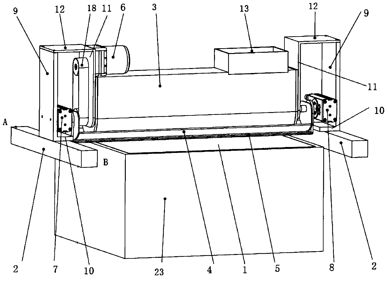
[0032] This embodiment provides a two-way powder spreading device for 3D printing process, such as Figure 1-Figure 2 As shown, it includes two connecting frames, which are one-to-one corresponding to the two guide rails 2 and are slidably connected; the powder container 3, which includes a feed port 13 and a discharge port, and the left and right sides of the powder container 3 are connected to the two The connecting frames are one-to-one corresponding and fixedly connected; the blanking plate 4 is rotatably arranged on the outside of the powder container 3 to open and close the discharge port; the scraper 5 for smoothing the powder is rotatably arranged On the outside of the powder container 3, to control the compactness of the powder; the stirring device, which is rotatably arranged inside the powder container 3, to break up and transport the powder; the first power unit, which is connected with the stirring device The transmission is connected to drive the stirring device ...

Embodiment 2

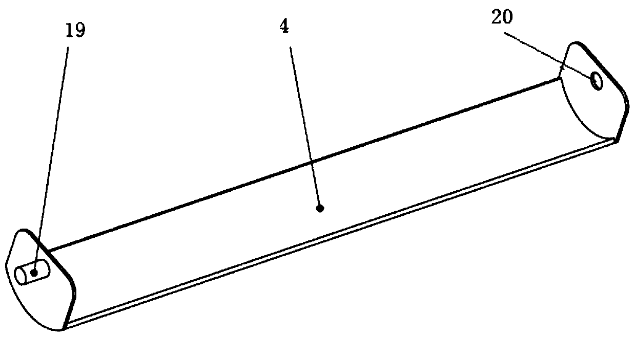
[0035] This embodiment includes all the technical features of Embodiment 1, the difference is that, as Figure 3-Figure 9As shown, the discharge port is arranged on the lower surface of the powder container 3, and the quantity of the discharge port in this embodiment is specifically 2, which are respectively the first discharge port 14 and the second discharge port 15, and the first discharge port The port 14 and the second discharge port 15 are arranged side by side in parallel, and optionally, the feed port 13 is arranged above the powder container 3, the lower surface of the powder container 3 is an arc surface, and the blanking plate 4 is an arc drop. The upper surface of the blanking plate 4 is attached to the lower surface of the powder container 3, and the blanking plate 4 rotates around the axis of the arc surface; the scraper 5 is a straight plate structure; the left and right sides of the blanking plate 4 are respectively A first side plate and a second side plate ar...

Embodiment 3

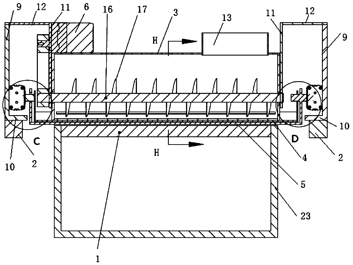
[0041] This embodiment includes all the technical features of Embodiment 1, the difference is that, as figure 2 As shown, the stirring device includes a central shaft 16 and a helical blade 17. The helical blade 17 is helically wound on the outer wall of the central shaft 16 along the length direction of the central shaft 16, and the two ends of the central shaft 16 run through the left and right sides of the powder container 3 respectively. The side is connected with the left and right sides of the powder container 3 respectively; With such arrangement, the stirring device can disperse and transport powder conveniently and quickly.


PUM


Abstract

The invention discloses a bidirectional powder pavement device used for a 3D printing process, and relates to the technical field of 3D printing. The bidirectional powder pavement device comprises twoconnecting frames, a powder container, a material falling plate, a scraping plate used for leveling powder and a stirring device. The two connecting frames are in one-to-one correspondence to and sliding connection with two guide rails. The powder container comprises a feeding opening and discharging openings, and the left side and the right side of the powder container are in one-to-one correspondence to and fixed connection with the two connecting frames. The material falling plate is rotationally arranged on the outer portion of the powder container so as to open and close the dischargingopenings. The scraping plate is rotationally arranged on the outer portion of the powder container so as to control the tightness degree of the powder. The stirring device is rotationally arranged inthe powder container so as to scatter and convey the powder. Compared with a vibration powder pavement manner, no noise is generated in the powder pavement process of the bidirectional powder pavementdevice used for the 3D printing process, the stirring device can effectively avoid powder caking, the material falling plate can precisely control the powder discharging amount, and the scraping plate can adjust the tightness degree of the paved powder.

Description

technical field [0001] The invention relates to the technical field of 3D printing, in particular to a bidirectional powder spreading device for 3D printing technology. Background technique [0002] For 3D printing equipment, the process is usually to lay a layer of powder or granular materials on the workbench. The area selected by the control software in the layer of powder is solidified and formed by means of adhesives, etc., and this area is usually the cross-section of the workpiece to be produced. In this way, the workpieces required for cumulative molding are printed layer by layer. The existing powder spreading device includes a vibrating structure and a scraper. A guide rail is provided on opposite sides of the workbench of the 3D printing equipment. The vibrating structure is slidably connected to each guide rail. On the working table of the equipment, the falling powder is smoothed with a scraper. This powder spreading method often has the problem of powder aggl...

Claims


Application Information

Patent Timeline
Patent Type & Authority Applications(China)
IPC IPC(8): B29C64/205B29C64/214B29C64/321B29C64/314B22F3/00B22F3/105B33Y30/00B33Y40/00B22F12/50B22F12/57B22F12/60
CPCB29C64/205B29C64/214B29C64/321B29C64/314B22F3/005B33Y30/00B33Y40/00B22F10/10B22F10/00B22F12/226B22F12/67B22F10/20Y02P10/25
Inventor 韩毅张龙
Owner 山东汇景信息科技有限公司
Why Eureka
Try Eureka