Concrete conveying device having heating function

A transportation device and function technology, applied in the field of concrete transportation devices with heating function, can solve the problems of the transportation device lacking heating function and difficult to solve the problem of heat preservation, and achieve the effects of lowering temperature, reducing heat loss and reducing residues

Inactive Publication Date: 2019-10-25
四川德程建设有限公司
View PDF8 Cites 0 Cited by
  • Summary
  • Abstract
  • Description
  • Claims
  • Application Information

AI Technical Summary

Problems solved by technology

[0002] In the construction of concrete in the alpine area, how to ensure that the concrete has a certain temperature during the mixing, transportation, and pouring process has always been a construction problem in the alpine area. The mixing and pouring process is relatively concentrated, and it is easier to solve the temperature problem. The current transportation device lacks The heating function makes it difficult to solve the problem of heat preservation during transportation

Method used


Image

  • Concrete conveying device having heating function
  • Concrete conveying device having heating function

Examples


Embodiment 1

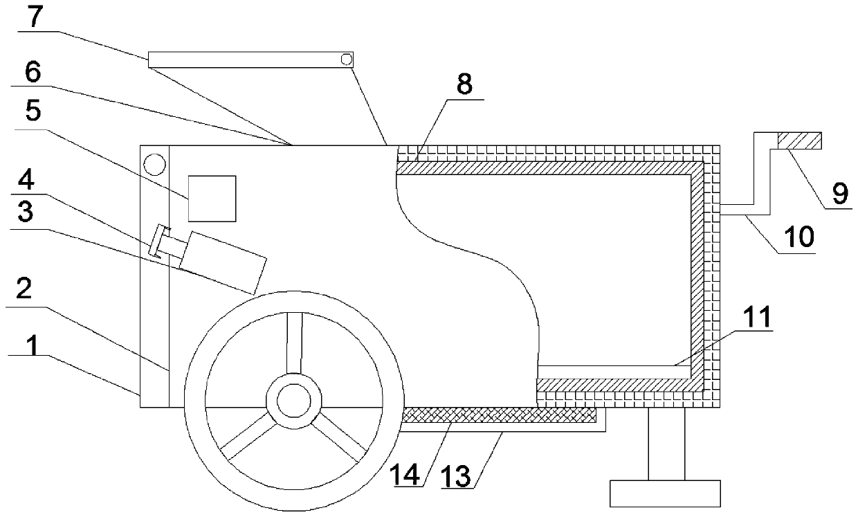
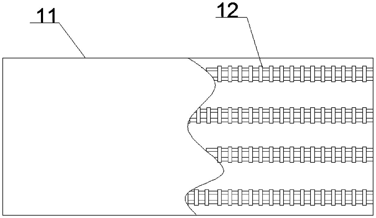
[0029] A concrete transportation device with a heating function, comprising a box body 2, a discharge cover plate 1 is arranged on one side of the box body 2, a storage battery 14 is arranged on the lower part of the box body 2, and an inlet is arranged on the upper part of the box body 2 A feed port 6, the feed port 6 is provided with a feed cover 7, the box 2 is provided with an insulating layer 8, the bottom wall of the box 2 is provided with a metal plate 11, and the metal plate 11 A radiation heating tube 12 is arranged inside, and the radiation heating tube 12 is electrically connected with a storage battery 14 .

[0030] working principle:

[0031] First, the feed cover 7 is opened, and concrete is loaded into the box body 2 through the feed port 6, and when the filling is completed, the feed cover 7 is closed. By setting the feeding cover plate 7, the feeding port 6 can be closed to prevent the hot air in the box body 2 from flowing out and lower the temperature of th...

Embodiment 2

[0033] On the basis of Example 1, a limit block 4 is arranged on the discharge cover 1, an automatic push rod 3 is arranged on the box body 2, and one side of the automatic push rod 3 moves with the limit block 4 connect. During use, the automatic push rod 3 is extended to push the limit block 4, and the limit block 4 rises to drive the discharge cover to rise to realize the opening of the discharge cover. In order to ensure the heating efficiency, the discharge cover 1 is relatively thick, and by setting the limit block 4 and the automatic push rod 3, the opening and closing of the discharge cover can be mechanized, reducing the use of manpower.

Embodiment 3

[0035] On the basis of Embodiment 1, the box body 2 is provided with a double-glazed observation window 5 . By setting the double-layer glass observation window 5, the situation in the box body 2 can be observed in time, the amount of concrete in the box body 2 can be known, and the practicability of the device can be improved.


PUM


Abstract

The invention discloses a concrete conveying device having a heating function. The concrete conveying device comprises a box body. One side of the box body is provided with a discharging cover plate,and the lower part of the box body is provided with a storage battery. The upper part of the box body is provided with a feeding port, the upper part of which is provided with a feeding cover plate. Athermal preservation layer is disposed in the box body, and a metal sheet is disposed on the bottom wall of the box body, and a radiation heating tube is disposed in the metal sheet, and is electrically connected with the storage battery. By arranging the feeding cover plate, the feeding port can be closed, and hot air in the box body can be prevented from flowing out, and the temperature of theconcrete cannot be reduced, and therefore the structure is simple, and the device is economic and practical. By arranging the storage battery and the radiation heating tube, the device has the heatingfunction, and can be used to provide heat energy for the concrete in Alpine-cold regions, and therefore the concrete can be prevented from solidified in low temperature, and the conveying problem ofthe concrete in the Alpine-cold region can be solved, and the use efficiency of the concrete can be improved.

Description

technical field [0001] The invention relates to the technical field of concrete transportation, in particular to a concrete transportation device with a heating function. Background technique [0002] In the construction of concrete in the alpine area, how to ensure that the concrete has a certain temperature during the mixing, transportation, and pouring process has always been a construction problem in the alpine area. The mixing and pouring process is relatively concentrated, and it is easier to solve the temperature problem. The current transportation device lacks The heating function has made it difficult to solve the problem of heat preservation during transportation. Contents of the invention [0003] The purpose of the present invention is to provide a concrete transport device with a heating function in view of the problem that the heat preservation problem in the transportation process has always been difficult to solve due to the lack of heating function of the ...

Claims


Application Information

Patent Timeline
Patent Type & Authority Applications(China)
IPC IPC(8): E04G21/02
CPCE04G21/02
Inventor 贺刚张贵霖王勇
Owner 四川德程建设有限公司
Why Eureka
Try Eureka