Automobile rope wheel type glass lifter system

A glass lifter and rope pulley technology, applied in the field of auto parts, can solve the problems of internal efficiency loss, large waste of motor performance, strict strength requirements, etc. Effect

Pending Publication Date: 2019-10-25
周唐丽
View PDF0 Cites 3 Cited by
  • Summary
  • Abstract
  • Description
  • Claims
  • Application Information

AI Technical Summary

Problems solved by technology

[0014] From the above analysis, it can be seen that, except for the internal efficiency loss, all the force required to lift the glass comes from the motor, and the motor torque requirement is large (generally 8N.m~12N.m), and the motor and The internal parts of the glass regulator mechanism are subjected to a large force (the bracket 2' is generally subjected to a steel wire rope force of about 300N), and the durability and creep requirements are high. performance waste

Method used


Image

  • Automobile rope wheel type glass lifter system
  • Automobile rope wheel type glass lifter system
  • Automobile rope wheel type glass lifter system

Examples


Embodiment 1

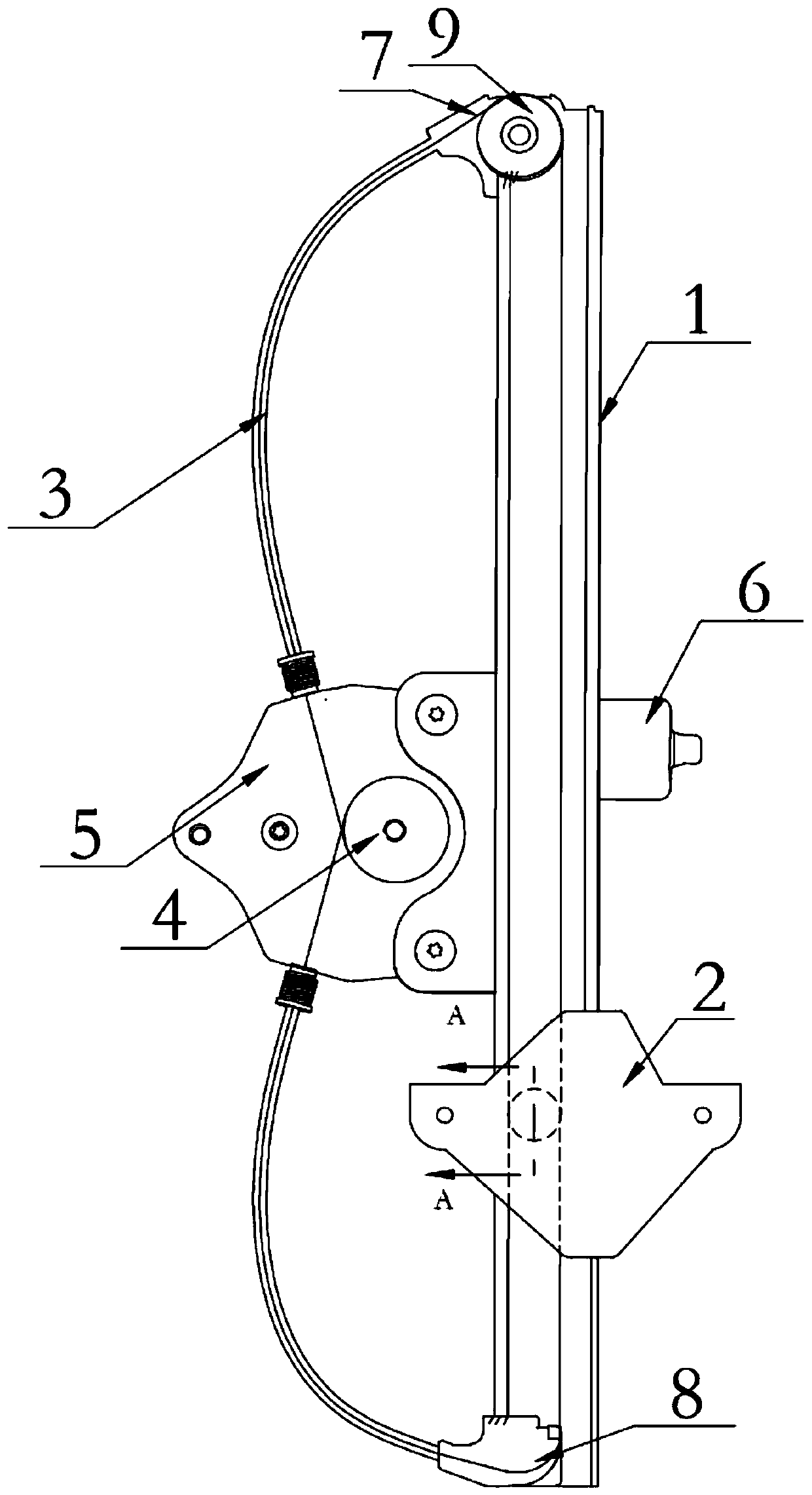
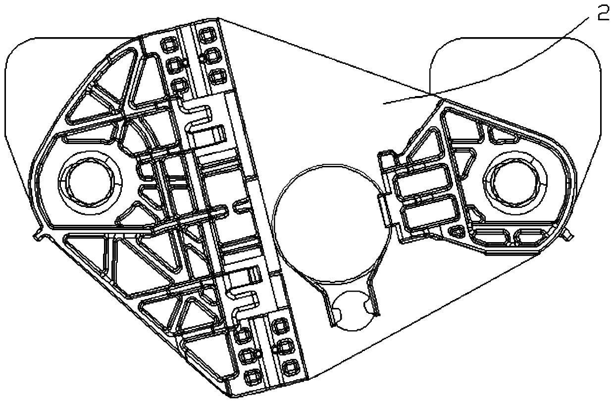
[0052] figure 2 It is a schematic diagram of the structure of the B-type monorail glass regulator, see figure 2 and image 3 . In this embodiment, the reel 4 of the driving part, the reel seat 5 and the motor 6 are assembled on the guide rail 1, and the output shaft of the motor 6 is connected with the reel 4 to drive the reel 4 to rotate forward or reversely. The upper guide 7 is arranged on the upper end of the guide rail 1 , the runner 9 is installed on the upper guide 7 , and the lower guide 8 is arranged on the lower end of the guide rail 1 . The dragline 3 includes two, respectively the first dragline and the second dragline, one end of the first dragline is fixed and wound on the reel 4 from one direction, and the other end passes through the runner 9 of the upper guide 7 1. After the upper guide part 21 of the bracket 2, its end is fixed on the upper end of the guide rail 1; one end of the second cable is fixed and wound on the reel 4 from the other direction, and...

Embodiment 2

[0055] Figure 4 It is a structural schematic diagram of a D-type single-track glass regulator. The difference from Embodiment 1 is that in this embodiment, the reel 4, reel seat 5 and motor 6 of the driving part are arranged on one side of the guide rail 1, and the motor 6 outputs The shaft is connected with the reel 4, and the reel 4 is driven to rotate forward or reversely. The overall structure is D-shaped.

Embodiment 3

[0057] Figure 5 It is a structural schematic diagram of a lower-end driven glass regulator. The difference from Embodiment 1 and Embodiment 2 is that in this embodiment, the reel 4, reel seat 5 and motor 6 of the driving part are arranged at the lower end of the guide rail 1. The output shaft of the motor 6 is connected with the reel 4 to drive the reel 4 to rotate forward or reversely. Because the reel 4 is arranged on the lower end of the guide rail 1, in this embodiment, the lower guide 8 is not provided, and one end of the cable 3 is fixedly wound on the reel 4, and the other end passes through the runner of the upper guide 7. 9. After the upper guide part 21 of the bracket 2, its end is fixed on the upper end of the guide rail 1; one end of the cable 4 is fixed and wound on the reel 4, and after passing through the lower guide part 22 of the bracket 2, the other end is fixed at the lower end of rail 1.


PUM


Abstract

The invention discloses an automobile rope wheel type glass lifter system which comprises a guide rail, a bracket, a motor, a winding wheel and an inhaul cable. An output shaft of the motor is connected with the winding wheel. The bracket and the guide rail are in sliding fit. A guide portion is arranged on the bracket. One end of the inhaul cable is fixed and wound on the winding wheel, and the other end of the inhaul cable is fixed to the end of the guide rail after passing through the guide portion. The guide portion is arranged on the bracket, one end of the inhaul cable is fixed and woundon the winding wheel, the other end of the inhaul cable is fixed to the end of the guide rail after passing through the guide portion, the output torque of the motor can be greatly reduced, under thesame conditions, the power requirements for glass ascending and descending can be met through the low-torque and small motor, the material selection requirements of glass lifter parts are low, and the structure is simple.

Description

technical field [0001] The invention relates to the technical field of auto parts, in particular to an automotive sheave-type window lifter system. Background technique [0002] At present, among the four door window lift system products of automobiles, the rope pulley glass lifter is widely used in the market because of its good flexibility, simple structure of parts and products, etc. The product function of the rope-wheel type glass lifter is to lift the glass, and it is mainly composed of a driving component, a wire rope, a guide rail (with or without), and a bracket. The rope wheel type glass lifter system is divided into a glass lifter with a guide rail and a glass lifter without a guide rail. The glass regulator with guide rail is divided into B type single track glass lifter, D type single track glass lifter, bottom drive type glass lifter, double track glass lifter, single track door formwork system, and double track door formwork system. The glass lifter without ...

Claims


Application Information

Patent Timeline
Patent Type & Authority Applications(China)
IPC IPC(8): E05F15/689
CPCE05F15/689E05Y2900/55
Inventor 祝彪祝瑜蔚
Owner 周唐丽
Why Eureka
Try Eureka