Mixed-flow pump

A mixed-flow pump and volute technology, which is applied in the direction of pumps, pump components, and parts of pumping devices for elastic fluids, etc., can solve the impact loss of the gap flow field in the rear pump chamber to the mainstream flow field, and the rear cover plate The large gap at the wheel rim affects the overall efficiency of the unit, etc., so as to reduce the secondary flow vortex and hydraulic loss, reduce the impact loss, and reduce the impact loss of the wheel rim.

Pending Publication Date: 2019-10-25
JIANGSU UNIV ZHENJIANG RES INST OF FLUID ENG EQUIP TECH +1
View PDF0 Cites 0 Cited by
  • Summary
  • Abstract
  • Description
  • Claims
  • Application Information

AI Technical Summary

Problems solved by technology

[0004] Since the mixed-flow pump is used as the inlet of the turbine impeller, there is a certain inclination angle, so after the fluid flows out radially from the outlet of the volute, the velocity changes in the direction and enters the impeller flow channel, causing a certain loss in the gap area, which affects the overall efficiency of the unit
At the same time, the gap between the outlet of the volute and the rim of the rear cover plate of the mixed-flow impeller is relatively large, resulting in a relatively large flow area between the gap flow field of the rear pump chamber and the mainstream flow field. Further increase the impact loss of the gap flow field in the rear pump chamber to the mainstream flow field
Therefore, the current mixed-flow pump is used as a turbine volute structure, which affects the efficiency of the unit to a certain extent.

Method used


Image

  • Mixed-flow pump
  • Mixed-flow pump
  • Mixed-flow pump

Examples


Embodiment

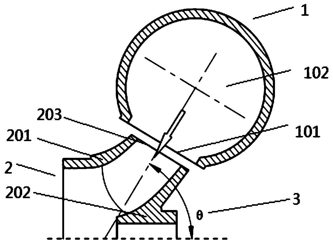
[0028] Such as figure 1 As shown, the embodiment of the present invention provides a mixed flow pump, which includes a volute 1 and an impeller 2; the outlet 101 of the volute communicates with the inlet 203 of the impeller;

[0029] The volute 1 is placed obliquely relative to the centerline of the impeller 2 , so that the centerline of the volute outlet 101 has a flow cone angle θ3 relative to the centerline of the impeller 2 .

[0030] It can be understood that in the volute matched with the turbine impeller of the mixed-flow pump in the prior art, the outlet design is mostly based on the volute outlet of the centrifugal pump used as the turbine, that is, the volute outlet is radial, and the specific volute The included angle between the centerline of the shell outlet and the axis of the rotating shaft is 90°. In the present invention, the outlet flow direction of the volute 1 can be changed by setting the flow cone angle θ3. On the one hand, according to the actual impell...


PUM


Abstract

The invention discloses a mixed-flow pump. The mixed-flow pump comprises a volute and an impeller; the outlet of the volute is communicated with the inlet of the impeller; the volute is inclined relative to a center line at a rotation shaft of the impeller so that a center line of the outlet of the volute has a flowing taper angle theta relative to a center line at the rotation shaft of the impeller. The inclination of the outlet of the volute is capable of playing a role in improving the incoming flow at the inlet of the mixed-flow pump as a turbine impeller, thereby decreasing the hydraulicloss and enhancing the performance of the mixed-flow pump as a turbine set. The mixed-flow pump can be widely applied in the large-flow and low-water head micro hydropower stations.

Description

technical field [0001] The invention relates to the fields of liquid pressure residual energy recovery and small-scale hydropower generation, in particular to a mixed-flow pump used as a turbine in a large-flow, low-head hydropower station. Background technique [0002] Liquid pressure energy is a renewable clean energy. With the increasing demand for energy in social development and the increasing awareness of energy conservation, the development and utilization of decentralized low-power liquid pressure energy will play an important role in building a resource-saving and environment-friendly society. The method of using the reverse pump to recover the residual pressure of the turbine has the advantages of small size, simple structure, convenient operation and maintenance, etc., and is widely used in energy-saving fields such as industrial processes and small hydropower. [0003] Different from the conventional Francis turbine, the mixed flow pump used as a turbine is usua...

Claims


Application Information

Patent Timeline
Patent Type & Authority Applications(China)
IPC IPC(8): F04D29/40F04D29/18F04D29/66
CPCF04D29/406F04D29/18F04D29/669
Inventor 戴韬杨孙圣
Owner JIANGSU UNIV ZHENJIANG RES INST OF FLUID ENG EQUIP TECH
Why Eureka
Try Eureka