
Anti-loosening ultrasonic transducer mounting structure and mounting method

An installation structure and transducer technology, applied in the direction of connecting components, threaded fasteners, screws, etc., can solve the problems of no major breakthrough in the anti-loosening structure of the installation cover, affecting the transduction effect of the transducer, and affecting the promotion and use. , to improve the anti-loosening effect, facilitate the combined installation and disassembly, and achieve a good combination effect.

Active Publication Date: 2019-10-25
DANDONG HEK TECH
View PDF13 Cites 2 Cited by
  • Summary
  • Abstract
  • Description
  • Claims
  • Application Information

AI Technical Summary

Problems solved by technology

Ultrasonic transducers used in cleaning tanks are often irreversibly damaged due to corrosion during long-term use, and the consequences are very serious
The patent number is CN206882303U, a Chinese utility model patent named "a transducer mounting cover for an ultrasonic cleaning machine", which discloses a transducer mounting cover structure for an ultrasonic cleaning machine that does not directly contact the cleaning liquid. The structure is simple and easy to install. It is convenient, but the installation cover and the transducer are only threaded. Long-term use will easily lead to loosening and falling off, which will affect the transducer's transduction effect and cause potential failure. However, due to the limitation of transducer structure and installation space, There is still no major breakthrough in the anti-loosening structure of this installation cover, which affects its popularization and use

Method used


Image

  • Anti-loosening ultrasonic transducer mounting structure and mounting method
  • Anti-loosening ultrasonic transducer mounting structure and mounting method
  • Anti-loosening ultrasonic transducer mounting structure and mounting method

Examples


Embodiment Construction

[0043] In order to clearly illustrate the technical features of the solution, the solution will be described below through specific implementation modes.

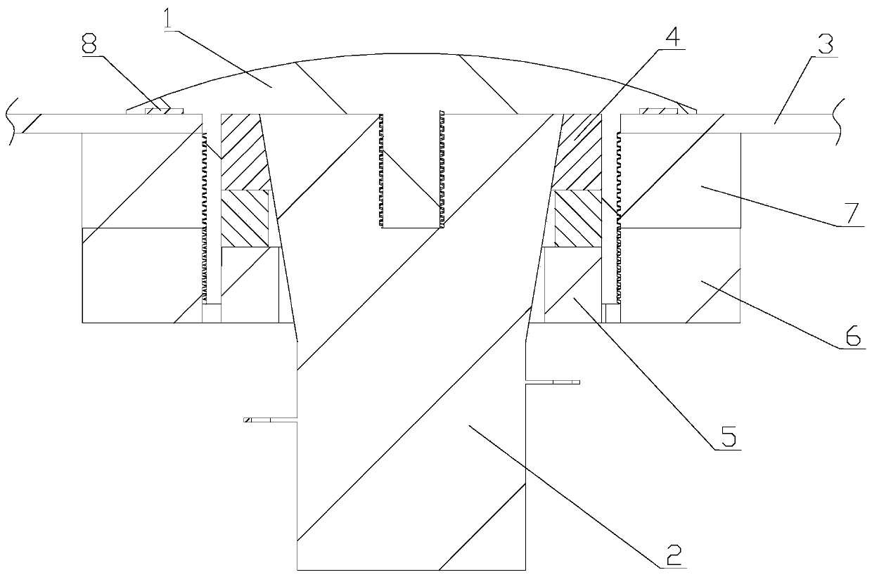
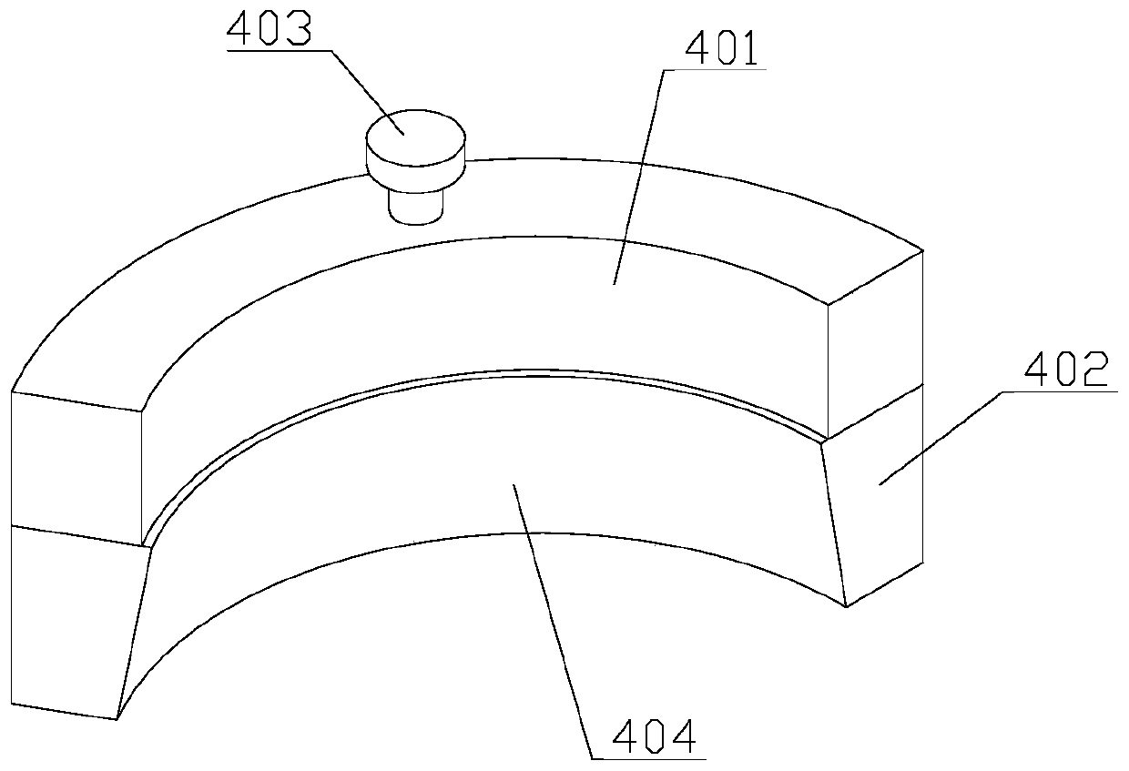
[0044] see Figure 1 to Figure 9 , the embodiment of the present invention provides an anti-loosening ultrasonic transducer installation structure, including a cleaning tank 3, an installation cap 1 set through the cleaning tank 3, a waterproof gasket 8 arranged between the installation cap 1 and the cleaning tank 3, and The connecting threaded sleeve 7 between the cleaning tank 3 and the mounting cap 1 is arranged on the transducer 2 on the mounting cap 1, which also includes an anti-loosening component disposed between the transducer 2 and the mounting cap 1;

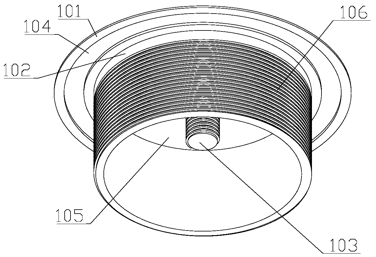
[0045] The mounting cap 1 includes an upper cover surface 101, a connecting ring 102 arranged at the center of the bottom surface of the upper cover surface 101, the axis of which is perpendicular to the upper cover surface 101, and an O-shaped ring located on the ...


PUM


Abstract

The invention discloses an anti-loosening ultrasonic transducer mounting structure and mounting method, and belongs to the technical field of transducer mounting. The anti-loosening ultrasonic transducer mounting structure comprises a cleaning groove, a mounting cap penetrating through the cleaning groove, a waterproof gasket arranged between the mounting cap and the cleaning groove, a connectingthread sleeve arranged between the cleaning groove and the mounting cap, and a transducer arranged on the mounting cap. An anti-loosening assembly arranged between the transducer and the mounting capis included. The anti-loosening ultrasonic transducer mounting structure has the beneficial effects that due to the anti-loosening ultrasonic transducer mounting structure, loosening and falling between the transducer and the mounting cap due to long-term use can be prevented, the service life is long, and the anti-loosening ultrasonic transducer mounting method facilitates dismounting and mounting, and operation is convenient.

Description

technical field [0001] The invention relates to the technical field of transducer installation technology, in particular to an anti-loosening ultrasonic transducer installation structure and installation method. Background technique [0002] Ultrasonic transducers are devices that use the piezoelectric effect of ceramics to convert mechanical vibrations generated by ultrasonic waves into electrical signals or generate mechanical vibrations under the drive of an electric field to emit ultrasonic waves. Sterilization and other functions have been more and more widely used in various industries, agriculture, household equipment, electronics, automobiles, rubber, printing, aircraft, food, hospitals and medical research. Ultrasonic transducers used in cleaning tanks are often irreversibly damaged due to corrosion during long-term use, and the consequences are very serious. The patent number is CN206882303U, a Chinese utility model patent named "a transducer mounting cover for an...

Claims


Application Information

Patent Timeline
IPC IPC(8): F16B39/12F16B39/02
CPCF16B39/02F16B39/12
Inventor 于日升
Owner DANDONG HEK TECH
Learn More