a burner

A burner and pipe body technology, applied in the field of cookers, to achieve low failure rate, improve ejection ability, and ensure normal operation

Active Publication Date: 2020-09-29
NINGBO FOTILE KITCHEN WARE CO LTD
View PDF8 Cites 0 Cited by
  • Summary
  • Abstract
  • Description
  • Claims
  • Application Information

AI Technical Summary

Problems solved by technology

In this structure, the nozzle and the injection pipe are in a horizontal position relationship, and there are problems mentioned above in use.

Method used


Image

  • a burner
  • a burner
  • a burner

Examples


Embodiment 1

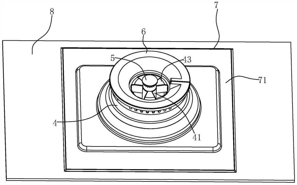
[0049]The burner can be installed in a cabinet for use. Usually, the upper surface of the cabinet has a panel 8, and the cabinet has an installation chassis on which the burner is installed.

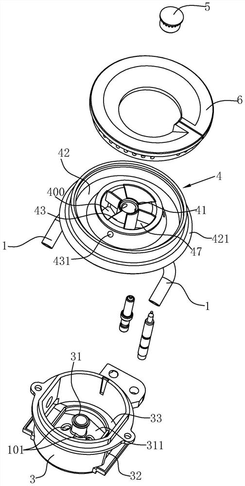
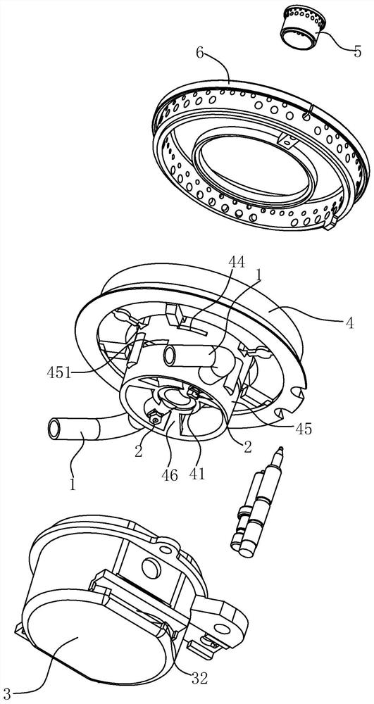
[0050] like Figure 1 to Figure 7 As shown, the burner in this embodiment includes a butt joint 1 , a nozzle 2 , a bottom cup 3 , a base 4 , an inner ring fire cover 5 , an outer ring fire cover 6 and a liquid pan 7 .

[0051] The liquid pan 7 is fixedly mounted on the panel 8 corresponding to the burner installation hole on the panel 8, and the liquid pan 7 also has an opening for the burner to be placed in. The liquid holding pan 7 in this embodiment has at least two stepped surfaces 71 , such that it is inclined downward from the inside to the outside along the radial direction.

[0052] The bottom cup 3 is cup-shaped as a whole, that is, the bottom cup 3 includes a bottom plate and a cup wall extending axially upward from the edge of the bottom plate. The installation edge is conne...

Embodiment 2

[0066] like Figure 8 As shown, the difference between this embodiment and Embodiment 1 is that the bottom of the liquid storage tank 400 gradually slopes downward along the radially inward direction, so that the bottom of the liquid storage tank 400 and the outer wall of the second tube body 41 A triangular liquid storage area is formed, which can store a certain amount of overflow liquid. An overflow hole 44 is defined at the lower end of the outer wall of the liquid storage tank 400 . In this way, the overflow that flows into the liquid storage tank 400 can first be collected in the triangular liquid storage area. Generally, when the amount of overflow is not large, the triangular liquid storage area can meet the storage of the overflow, which is convenient for storage. Post cleanup. When there is a large amount of overflow, in order to avoid the overflow from blocking the fire hole of the inner ring fire cover 5 and the flameout, when the overflow in the liquid storage t...


PUM


Abstract

The invention relates to a burner. The burner comprises an ejector tube, wherein the ejector tube is provided with an ejection port, and further comprises a butt joint tube connected with a gas tube,wherein a nozzle is arranged on the butt joint tube, and the nozzle faces the ejection port and is arranged above the ejection port. According to the burner, the nozzle is arranged above the ejectionport, so that the nozzle is in an inverted state, an ejection path is formed into a bent circuit segment, the ejection path is lengthened, the ejection capability is improved, gas and primary air canbe fully mixed, and the burning efficiency is improved. In addition, due to the fact that the nozzle is in an inverted state, the nozzle is not easy to block even when spilled liquid flows to the nozzle.

Description

technical field [0001] The invention relates to the technical field of cookers, in particular to a burner. Background technique [0002] Existing burners mainly include two types of burners, the upper air inlet burner and the lower air inlet burner. The bottom air intake burner has high primary air injection efficiency and sufficient premixing, which can effectively preheat the air, but it is easy to turn off the flame when the cabinet door is opened and closed, and if the cabinet does not open the air inlet, there will be a hidden danger of insufficient primary air. The upper air inlet burner on the existing market is limited by its structure and cannot have a very long ejector tube like the lower air inlet burner. For example, the Chinese utility model patent "A Waterproof upward air intake burner", this type of upward air intake burner has problems such as short primary air injection distance, insufficient injection, insufficient premixing space, and cannot effectively p...

Claims


Application Information

Patent Timeline
Patent Type & Authority Patents(China)
IPC IPC(8): F23D14/04F23D14/64F24C15/14F23D14/58
CPCF23D14/04F23D14/58F23D14/64F24C15/14
Inventor 邵海忠
Owner NINGBO FOTILE KITCHEN WARE CO LTD
Why Eureka
Try Eureka