
Power battery structure with automatic pressure relief

A power battery and automatic drain technology, applied in structural parts, battery pack parts, batteries, etc., can solve the problems of accelerating the chemical reaction of the battery cell, battery bulging, and copper precipitation in the negative electrode, achieving superior technical and economical efficiency and compact coordination. , easy to use effect

Pending Publication Date: 2019-10-25
中山市润烨新能源科技有限公司
View PDF0 Cites 1 Cited by
  • Summary
  • Abstract
  • Description
  • Claims
  • Application Information

AI Technical Summary

Problems solved by technology

Usually, when the cell is overcharged or slightly overcharged for many times for a long time, gas will be produced inside the cell and gradually accumulate to make the cell swell. In the same discharge process, over-discharge will cause copper deposition at the negative electrode, which will also cause gas to be generated inside the cell.
In addition, long-term high temperature will accelerate the chemical reaction inside the battery cell, and gas will be produced for a long time, causing problems such as battery swelling; in order to use the power battery more safely, we have developed a battery cover structure that can automatically release gas

Method used

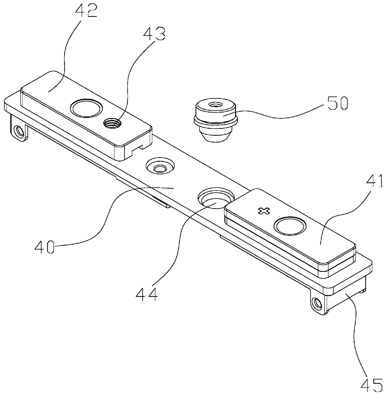
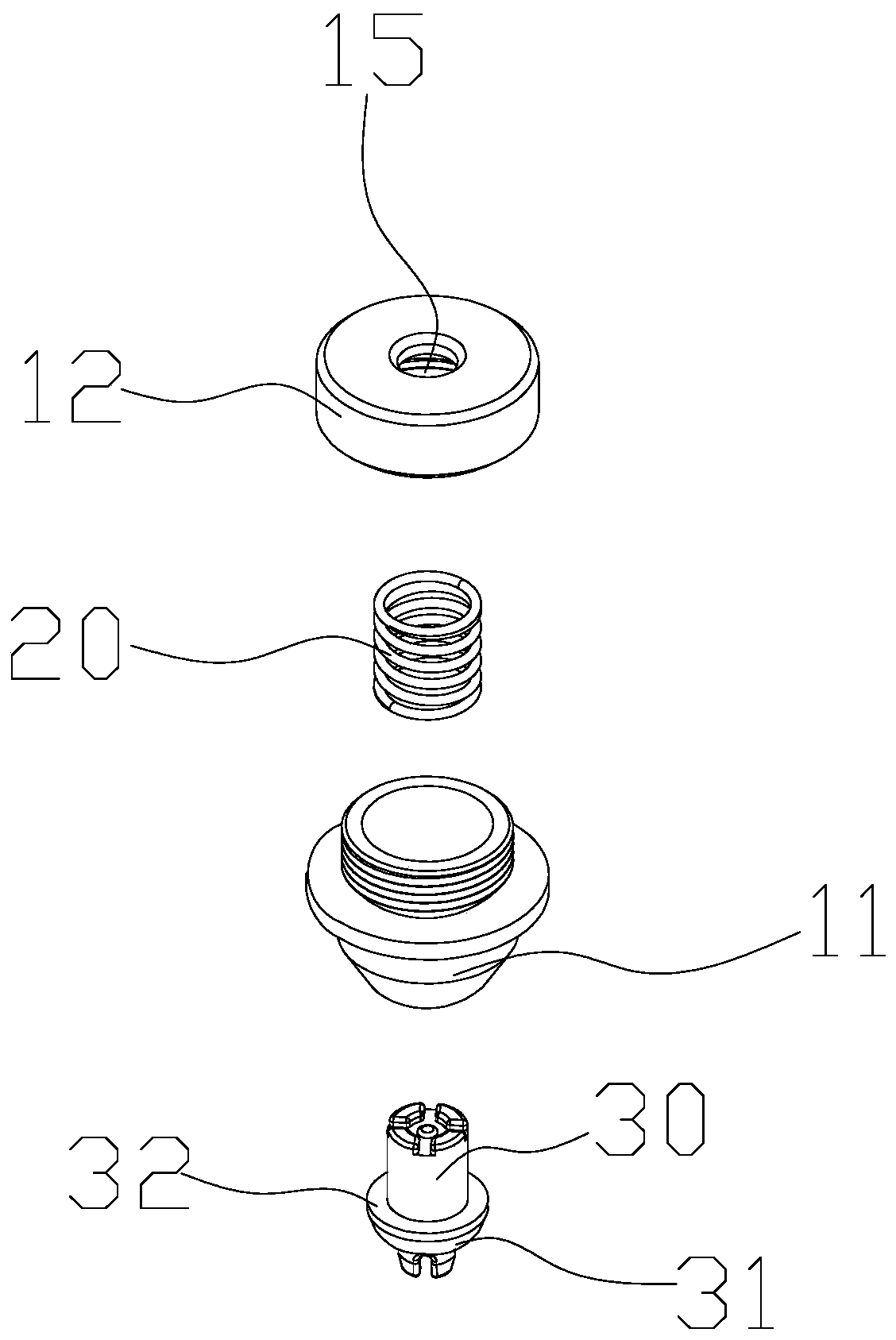
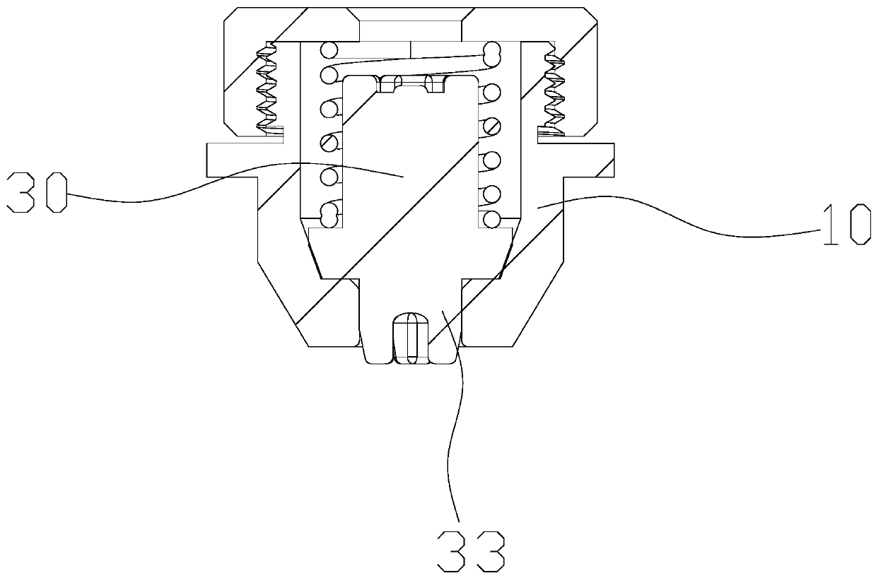

Image

  • Power battery structure with automatic pressure relief
  • Power battery structure with automatic pressure relief
  • Power battery structure with automatic pressure relief

Examples


Embodiment Construction

[0021] Embodiments of the present invention are described in detail below, examples of which are shown in the drawings, wherein the same or similar reference numerals represent the same or similar elements or elements having the same or similar functions throughout.

[0022] In the present invention, unless otherwise clearly specified and limited, if there are terms "assembled", "connected" and "connected", the terms should be interpreted in a broad sense, for example, it can be a fixed connection, a detachable connection, or an integral ground connection; it can also be a mechanical connection; it can be directly connected, or connected through an intermediary, or two components can be connected internally. Those of ordinary skill in the art can understand the specific meanings of the above terms in the present invention according to specific situations.

[0023] The technical solutions and beneficial effects of the present invention will be clearer and more definite by furth...


PUM


Abstract

The invention discloses a power battery structure with automatic pressure relief. The structure includes a battery cover plate and an automatic pressure relief valve, wherein the battery cover plate includes a positive end portion and a negative end portion, a pressure relief port is arranged between the positive end portion and the negative end portion, the automatic pressure relief valve is mounted in the pressure relief port and includes a fixing sleeve, an elastic member and a moving plug body, the fixing sleeve has a pressure relief chamber, the fixing sleeve includes an exhaust port andan air inlet, the pressure relief chamber is in communication with the exhaust port and the air inlet, the moving plug body has a plug, the plug is movably plugged in the air inlet, the moving plug body is disposed in the pressure relief chamber, the elastic member is sleeved on the moving plug body, the elastic member is driven through movement of the moving plug body to change the potential energy of the elastic member, and connection state switching of the plug and the air inlet is achieved through potential energy transition between the moving plug body and the sleeved elastic member. Thestructure is advantaged in that the structure is simple, compact to match, is convenient to use and is reasonable to design, so the structure has excellent technical and economic properties.

Description

【Technical field】 [0001] The invention mainly relates to a power battery structural part with automatic pressure relief. 【Background technique】 [0002] The swelling of the battery cell is an early warning of damage to the battery cell or a safety problem. It needs to be paid enough attention when using the battery system. If the protection measures are proper, it can become an advantage of the safe use of the pouch battery. Usually, when the cell is overcharged or slightly overcharged for many times for a long time, gas will be produced inside the cell and gradually accumulate to make the cell swell. In the same discharge process, over-discharge will cause copper deposition at the negative electrode, which will also cause gas to be generated inside the cell. In addition, long-term high temperature will accelerate the internal chemical reaction of the battery, and long-term gas production will cause problems such as battery swelling; in order to use the power battery more sa...

Claims


Application Information

Patent Timeline
IPC IPC(8): H01M2/12
CPCH01M2200/20H01M50/394H01M50/333Y02E60/10
Inventor 蹇印军彭建豪
Owner 中山市润烨新能源科技有限公司
Learn More