Subway tunnel construction railcar facilitating realization of regular cable laying

A technology for cable laying and tunnel construction, which is used in cable laying equipment, transportation of filamentous materials, and thin material handling, etc., can solve the problems of cable damage, large volume, and high labor intensity.

Pending Publication Date: 2019-10-25
SOUTHWEST JIAOTONG UNIV
View PDF0 Cites 1 Cited by
  • Summary
  • Abstract
  • Description
  • Claims
  • Application Information

AI Technical Summary

Problems solved by technology

When the cable reel does not match the speed of the vehicle, the cable is too tight or too loose, especially when turning, the efficiency of paying off the cable is very low, and it is easy to cause damage to the cable
[0005] (2) The length of the pay-off arm is generally 3 meters and the weight is about 1.5 tons. W

Method used


Image

  • Subway tunnel construction railcar facilitating realization of regular cable laying
  • Subway tunnel construction railcar facilitating realization of regular cable laying
  • Subway tunnel construction railcar facilitating realization of regular cable laying

Examples


Embodiment 1

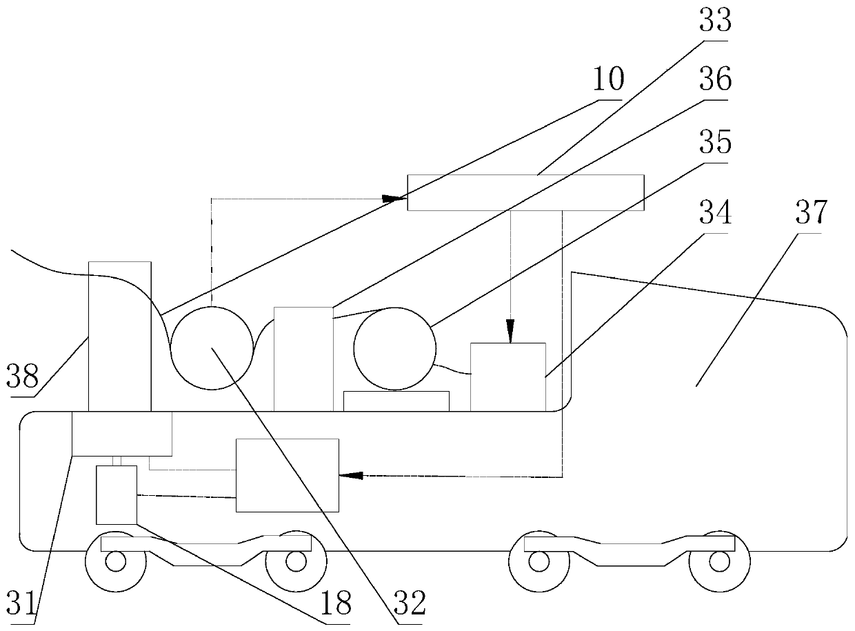
[0043] Such as figure 1 , figure 2 and Figure 4 As shown, the subway tunnel construction rail car that is convenient to realize regular cable laying includes a rail car body, and the rail car body is provided with a pay-off arm 38, and also includes a cable restraint device installed on the pay-off arm 38. The cable restraint device includes a support 39, a support 40, a cable guide 42 and a wire binding machine 36, the support 39 is fixed on the pay-off arm 38, the support 40 is rotatably connected to the support 39, and also includes A locking member 41 for fixing the bracket 40 relative to the support 39;

[0044] Both the cable guide 42 and the wire binding machine 36 are fixedly installed on the bracket 40 , and the cable input end of the cable guide 42 is connected with the cable input end of the wire binding machine 36 .

[0045] In the prior art, for subway tunnel construction, the number of cables used to lay on the cable support 40 is generally multiple. Now, a ...

Embodiment 2

[0050] The present embodiment is further limited on the basis of embodiment 1, as figure 1 , figure 2 and Figure 4 As shown, the cable guide 42 is a cylinder with one end facing the cable input end of the binding machine 36, the support 39 includes a cylindrical column, and the lower end of the bracket 40 is also provided with a round hole, and the column clearance fits In the circular hole, the locking member 41 is a locking bolt threaded on the bracket 40 . This solution provides a specific form of the cable guide 42 and a matching manner between the support 39 and the bracket 40 . As a person skilled in the art, the end of the locking bolt presses the support 39 , and the support 39 and the bracket 40 can be fixed by using friction force.

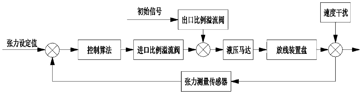
[0051] In order to make the cable restraint device have the guiding function of the cable movement trajectory, and at the same time measure the tension of the cable during the transmission process, it is arranged to: further include...

Embodiment 3

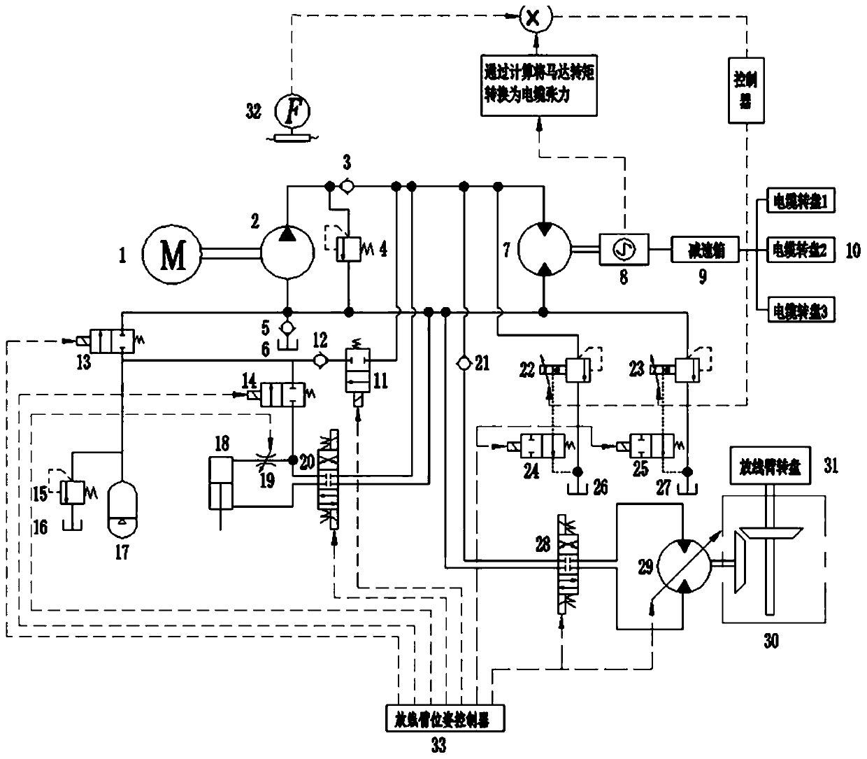
[0055] The present embodiment is further limited on the basis of embodiment 1, as Figure 1 to Figure 4 As shown, it also includes a cable reel 35, a reel drive system 34, and a pay-off arm 38 drive system installed on the rail car body. The reel drive system 34 is used to drive the cable reel 35 to rotate, and the pay-off The arm 38 drive system is used to drive the pay-off arm 38 to lift and rotate. The wire reel drive system 34 and the pay-off arm 38 drive system are all electro-hydraulic drive systems, and an accumulator 17 is arranged in the electro-hydraulic drive system. The accumulator 17 is connected to the pipeline at the outlet end of the hydraulic pump 2 in the electro-hydraulic drive system: when the hydraulic pump 2 is working, the accumulator 17 can store the pressure energy from the hydraulic pump 2, and the accumulator 17 can Release energy to actuators in electrohydraulic drive systems.

[0056] In the prior art, for railcars used for subway cable laying, th...


PUM


Abstract

The invention discloses a subway tunnel construction railcar facilitating the realization of regular cable laying. The railcar includes a railcar body provided with a pay-off arm. The railcar also includes a cable restraint device installed on the pay-off arm. The cable restraint device includes a support, a bracket, a cable guide and a binding machine. The support is fixed on the pay-off arm, andthe bracket can be rotationally connected to the support. The railcar also includes a locking piece for fixing the bracket relative to the support. The cable guide and the binding machine are fixedlyinstalled on the bracket, and the cable input end of the cable guide is connected with the cable input end of the binding machine. By adopting the structure design of the railcar, multiple stands ofcables can be laid synchronously, and regular cable wiring can be obtained on the cable bracket.

Description

technical field [0001] The invention relates to the technical field of cable wiring equipment, in particular to a rail car for subway tunnel construction that facilitates regular cable laying. Background technique [0002] In order to ensure the normal power supply inside the subway, cables need to be laid in the tunnel of the subway section, and the above cables generally extend along the extension direction of the tunnel. In order to improve the efficiency of cable wiring and reduce the labor intensity of wiring, in the prior art, a rail car that can move along the track in the tunnel is generally used as the carrier of the cable laying equipment, that is, the rail car moves along the track. The release device on it releases the cable to the cable bracket. A pay-off arm and a wire reel are installed on the existing rail car, and the motor drives the wire reel to pay out the wires, and then the pay-off arm is manually adjusted so that the cable is placed on the cable suppo...

Claims


Application Information

Patent Timeline
IPC IPC(8): H02G1/06B65H49/18
CPCB65H49/18B65H2701/34H02G1/06
Inventor 刘桓龙谢迟新陈冠鹏
Owner SOUTHWEST JIAOTONG UNIV
Why Eureka
Try Eureka