A spray cooling device combining steam chamber and composite microstructure

A composite microstructure and spray cooling technology, which is used in cooling/ventilation/heating transformation, electrical equipment structural parts, electrical components, etc. Complex heat exchange technology and other problems, to achieve the effect of improving the stretchability of the liquid film, improving the heat dissipation effect, and reducing the thermal resistance

Active Publication Date: 2020-12-04
NANJING UNIV OF SCI & TECH
View PDF11 Cites 0 Cited by
  • Summary
  • Abstract
  • Description
  • Claims
  • Application Information

AI Technical Summary

Problems solved by technology

However, due to the complexity of spray cooling heat transfer technology, there are many factors affecting its heat transfer performance.
On the one hand, the high heat flux density of electronic components is likely to cause local drying of the heat transfer surface, which affects the critical heat flux density; on the other hand, the current spray heat transfer surface mostly adopts simple geometric microstructures such as pin ribs and grooves Although the surface heat transfer performance has been improved to a certain extent, the extension ability of the liquid film on the spray surface is not enough to achieve higher heat transfer performance, and it is difficult to meet the heat dissipation requirements of higher heat flux density

Method used


Image

  • A spray cooling device combining steam chamber and composite microstructure
  • A spray cooling device combining steam chamber and composite microstructure
  • A spray cooling device combining steam chamber and composite microstructure

Examples


Embodiment Construction

[0024] The present invention will be described in further detail below with reference to the accompanying drawings.

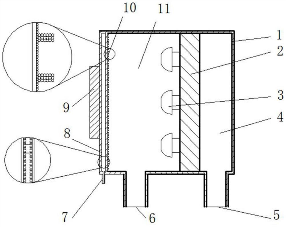
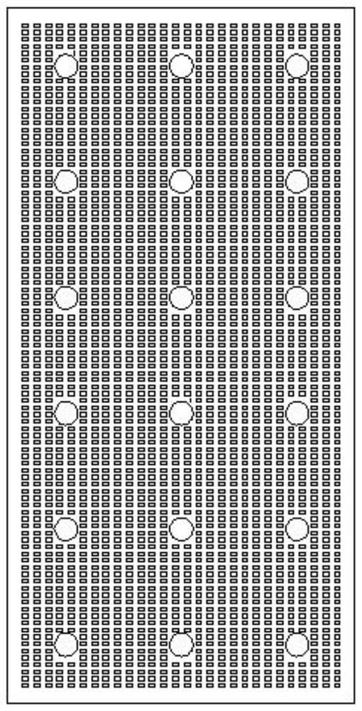
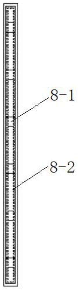
[0025] combine figure 1 , a spray cooling device combining a steam chamber and a composite microstructure, comprising a spray chamber 1, a spray chamber liquid inlet pipe 5, a spray chamber liquid outlet pipe 6, and a steam chamber 8. The spray chamber body 1 and the steam chamber 8 Set as one piece, the spray chamber 1 includes an orifice plate 2 , an array nozzle 3 and a composite microstructure 10 located therein, and the orifice plate 2 divides the spray chamber 1 into a buffer chamber 4 and a spray chamber 11 , the function of the buffer chamber 4 is to provide a uniform liquid inlet pressure to the nozzles 3 arranged in the array, the liquid inlet pipe 5 of the spray chamber is communicated with the buffer chamber 4, the outlet pipe 6 of the spray chamber is communicated with the spray chamber 11, The spray chamber body, the spray chamber liquid inlet pi...


PUM

PropertyMeasurementUnit
particle diameteraaaaaaaaaa
lengthaaaaaaaaaa

Abstract

The invention discloses a spray cooling device combining a steam cavity and a composite microstructure. The device comprises a spray chamber, a spray chamber liquid inlet pipe, a spray chamber liquidoutlet pipe and a steam chamber, wherein the spray chamber and the steam chamber are integrally arranged; the spray chamber comprises a spray orifice plate, array nozzles and a composite microstructure which are positioned in the spray chamber; the spray orifice plate divides the spray chamber into a buffer chamber and a spray chamber; the spray chamber liquid inlet pipe is communicated with the buffer chamber; the spray chamber liquid outlet pipe is communicated with the spray chamber, the composite microstructure is arranged on the wall face, opposite to the array nozzle, in the spray chamber, the composite microstructure comprises a bottom layer liquid absorption core arranged on the wall face opposite to the array nozzle and a plurality of rib-shaped liquid absorption cores arranged onthe bottom layer liquid absorption core, and a phase change working medium is sealed in the steam chamber. The steam chamber expands heat generated by a heat source to the spraying wall face with a large area, the heat exchange performance of the wall face is improved through multi-nozzle array spraying, and the two-phase heat exchange capacity of spraying is improved through combination of the steam chamber and a composite microstructure enhanced heat transfer mode.

Description

technical field [0001] The invention belongs to the technical field of spray cooling, and in particular relates to a spray cooling device combining a steam cavity and a composite microstructure. Background technique [0002] With the development of high-performance, high-efficiency, high-integration and high-reliability of aerospace electronic components, the problem of heat dissipation with high heat flux density of electronic components follows, especially the heat flux density of airborne equipment can reach 100~ 1000W / cm 2 . High heat flux density heating problems may cause unstable operation or even failure of electronic components. The problem of high heat flux density has become one of the technical bottlenecks restricting the development of electronic components. Conventional air natural convection or forced convection heat transfer coefficient is only 2 ~ 250W / (m 2 Within the range of K), it is difficult to meet the heat dissipation requirements; jet cooling has...

Claims


Application Information

Patent Timeline
Patent Type & Authority Patents(China)
IPC IPC(8): H05K7/20
CPCH05K7/20345
Inventor 胡定华李强张志伟
Owner NANJING UNIV OF SCI & TECH
Why Eureka
Try Eureka