Novel food spray gun
A spray gun and food technology, applied in the fields of food science, food forming, baked food processing, etc., can solve the problems of danger, high processing cost, residual high-pressure gas, etc., and achieve the effect of safe use process and simple structure
- Summary
- Abstract
- Description
- Claims
- Application Information
AI Technical Summary
Problems solved by technology
Method used
Image

Examples
Embodiment Construction
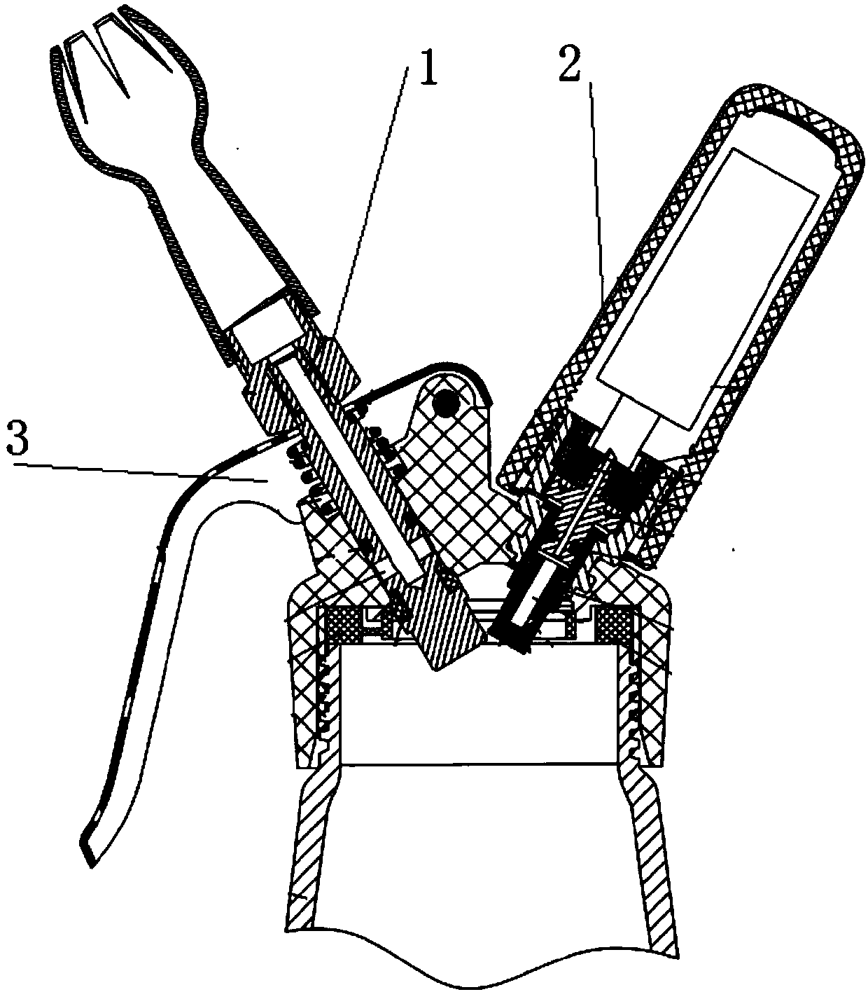
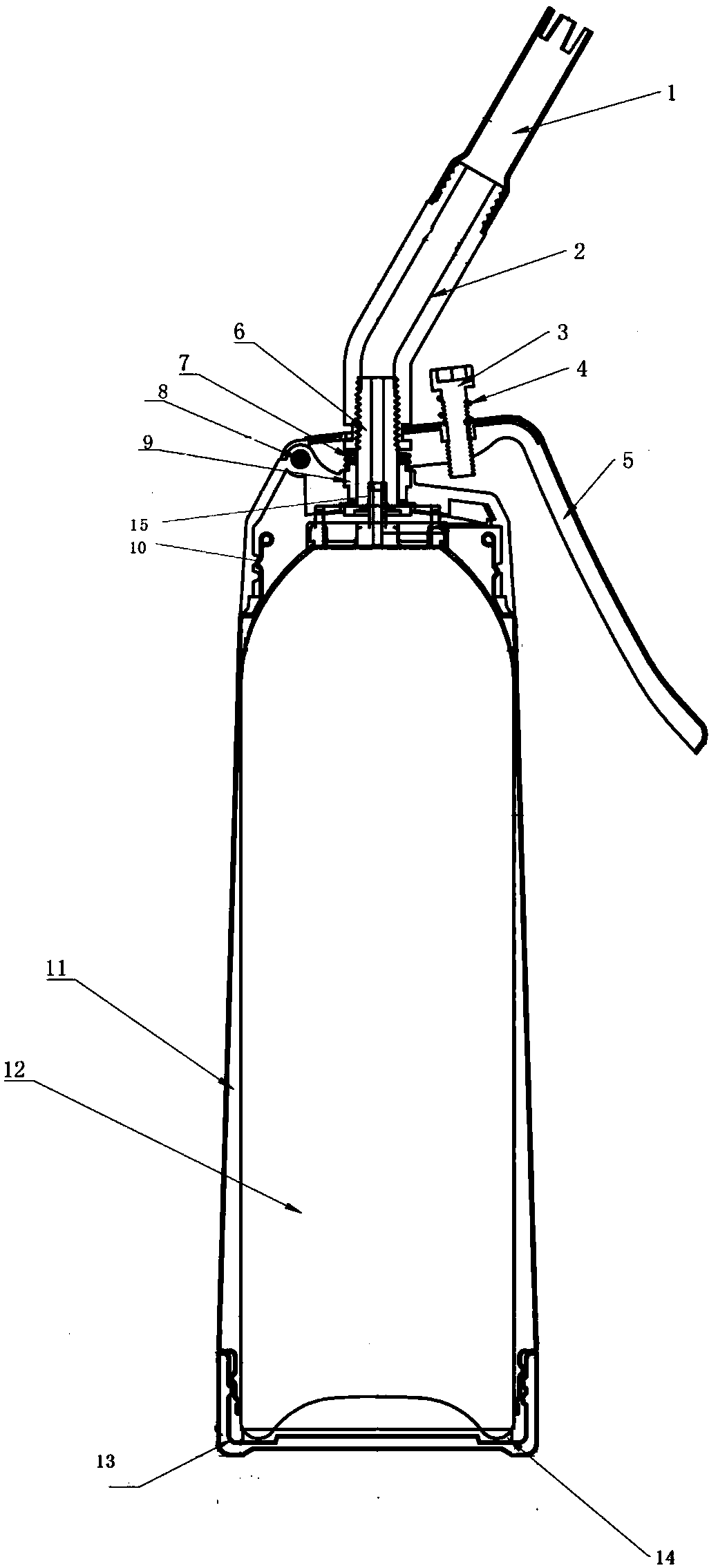
[0030] see figure 2 , according to the food spray gun provided by the invention, including a flower nozzle 1, an elbow 2, a limit screw 3, a limit screw spring 4, a handle 5, a food ejection tube 6, a handle compression spring 7, a handle pin 8, and a fixed sleeve 9 , Limiting device 10, spray gun bottle body 11, pressure food tank 12, lid 13, gasket 14, pressure food tank nozzle 15.
[0031] Compared with the previous cream gun, this structure is provided with a food ejection pipe and a pressing structure on the gun head. Compared with the prior art, the high-pressure gas inlet device and pressure relief device are reduced, and the structure is simpler.
[0032] The pressure food tank 12 is produced in advance, and pressure gas and food are mixed in the pressure tank. It can be filled with different food ingredients as needed, such as cream or coffee essence, etc. During use, the pressure food tank 12 is directly put into the gun body of the spray gun for use, and after us...
PUM
 Abstract
Description
Claims
Application Information