
electric VALVE AND refrigerating CYCLE SYSTEM

A technology of electric valves and valve ports, which is applied in the direction of irreversible cycle compressors, lift valves, refrigerators, etc., can solve the problems of sliding deterioration of valve parts, deformation and deformation of guide holes, etc., and achieve the effect of stable action characteristics

Active Publication Date: 2019-10-29
SAGINOMIYA SEISAKUSHO CO LTD
View PDF10 Cites 0 Cited by
  • Summary
  • Abstract
  • Description
  • Claims
  • Application Information

AI Technical Summary

Problems solved by technology

Therefore, there is a problem that the main body part is deformed (contracted) in the direction intersecting the axis, and the guide hole is deformed, thereby deteriorating the slidability of the valve member.

Method used


Image

  • electric VALVE AND refrigerating CYCLE SYSTEM
  • electric VALVE AND refrigerating CYCLE SYSTEM
  • electric VALVE AND refrigerating CYCLE SYSTEM

Examples


Embodiment Construction

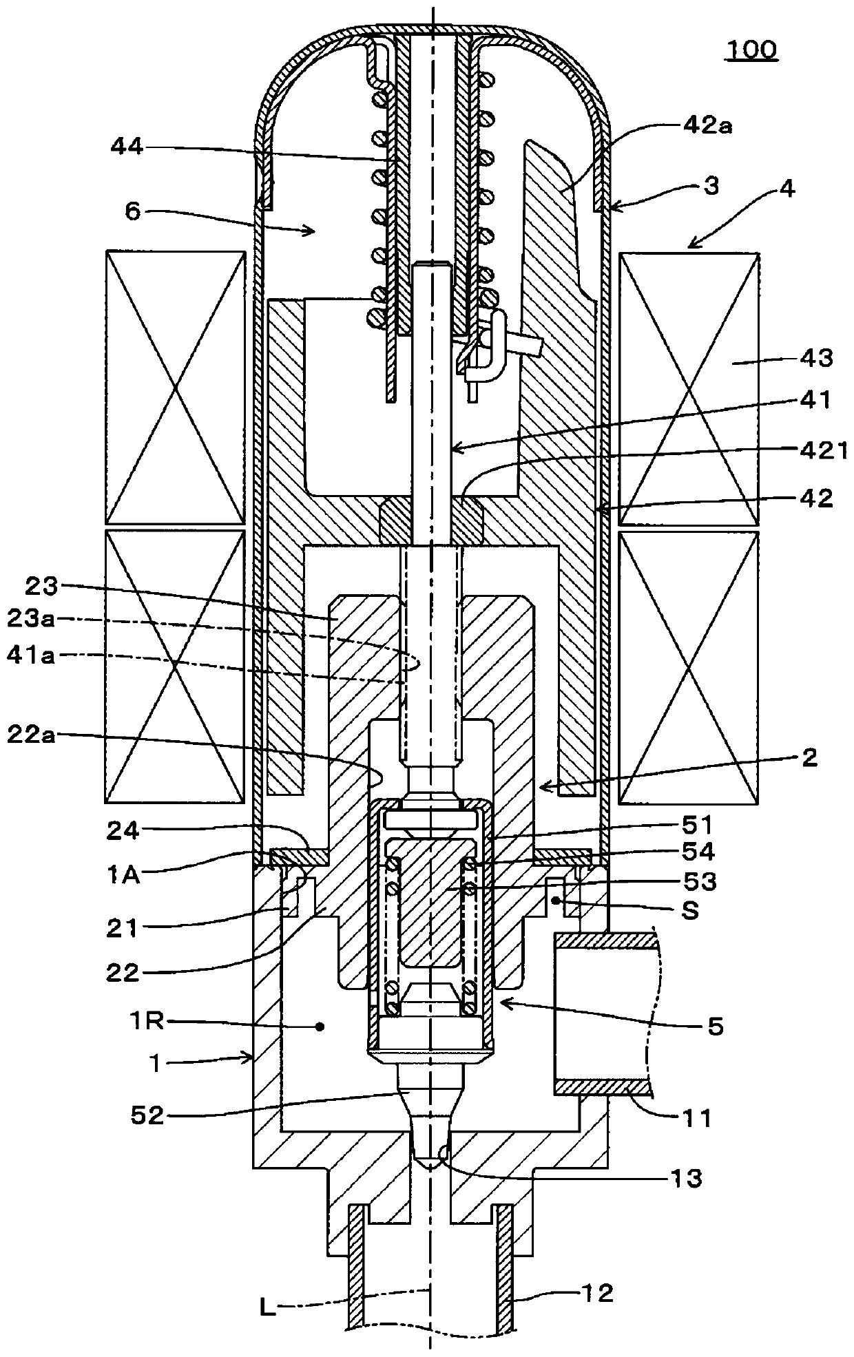
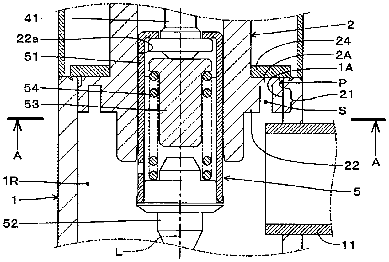
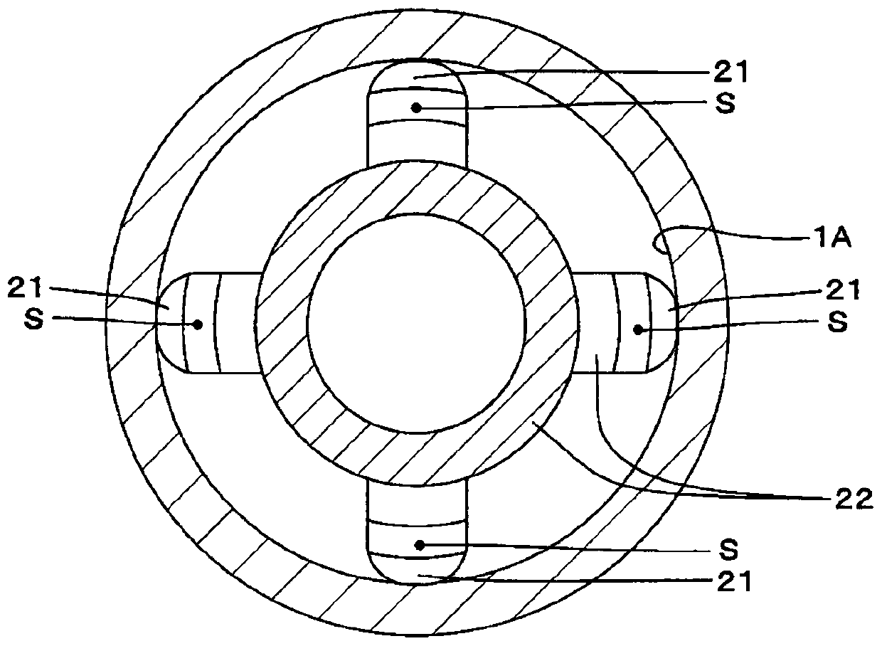
[0032] Next, embodiments of an electric valve and a refrigeration cycle system according to the present invention will be described with reference to the drawings. figure 1 is a longitudinal sectional view of the electric valve of the first embodiment, figure 2 It is an enlarged cross-sectional view of an assembled portion of a valve casing and a guide member in the electric valve of the first embodiment, image 3 yes means figure 2 The A-A sectional view of the valve housing and guide parts, Figure 4 yes figure 2 An enlarged view of the main part. Also, the concept of "up and down" in the following description is the same as figure 1 The upper and lower correspondences in the figure.

[0033] The electric valve 100 includes a valve case 1 , a guide member 2 , a sealing case 3 , a stepping motor 4 as a “motor unit”, and a valve member 5 .

[0034] The valve case 1 is formed in a substantially cylindrical shape from metal such as brass or stainless steel, for example,...


PUM


Abstract

The present invention provides an electric valve and a refrigerating cycle system. In an electric valve in which a guide member (2) having a guide hole (22a) for guiding the valve member (5) is press-fitted into the valve housing (1), the deformation of the guide hole (22a) of the guide member (2) is prevented. The connecting portion (2A) connects the pressing portion (21) crimped to the inner peripheral surface (1A) of the opening portion of the valve housing (1) with the outer peripheral portion of the guide hole (22a), that is, the guide portion (22) is connected to form a guide Part (2). In the guide member (2), a non-connection space (S) is formed between the press-in portion (21) and the guide portion (22) as a non-transmission portion having a length in the direction of the axis (L). The non-connection space (S) serving as the non-transmitting portion is used to transmit the reaction force from the valve housing (1) acting on the press-in portion (21) without directing the portion (22).

Description

technical field [0001] The present invention relates to an electric valve used in a refrigerating cycle system and the like, and the refrigerating cycle system. Background technique [0002] Conventionally, as such an electric valve, there is a technique disclosed in Japanese Patent No. 6214488 (Patent Document 1), for example. In this electric valve, the rotor shaft of the stepping motor is threadedly combined with the internal threaded part to form a screw transmission mechanism. Through the rotation of the rotor shaft, the rotor shaft and the valve part move forward and backward through the screw transmission mechanism, and the valve part is used to control the opening of the valve port. degree structure. In addition, in this electric valve, the valve body is centered with respect to the valve housing by pressing and fixing the internal thread member into the valve housing. [0003] prior art literature [0004] Patent Document 1: Japanese Patent No. 6214488 [0005] ...

Claims


Application Information

Patent Timeline
IPC IPC(8): F16K1/00F16K1/32F16K31/02F25B1/00
CPCF16K1/00F16K1/32F16K31/02F25B1/00
Inventor 小林一也中川大树
Owner SAGINOMIYA SEISAKUSHO CO LTD
Learn More