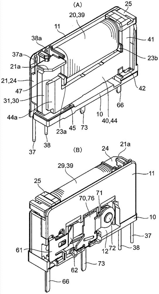
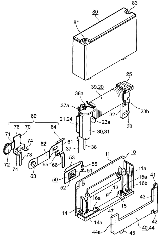
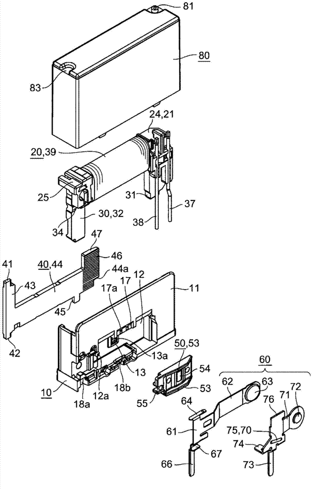
Electromagnetic relay

A technology of electromagnetic relays and electromagnets, applied in electromagnetic relays, relays, detailed information of electromagnetic relays, etc., can solve the problems of inability to obtain electromagnetic relays, easy to produce fluctuations, etc., and achieve increased degrees of freedom, stable operating characteristics, and productivity. high effect

Active Publication Date: 2014-12-10
ORMON CORP
View PDF8 Cites 2 Cited by
  • Summary
  • Abstract
  • Description
  • Claims
  • Application Information

AI Technical Summary

Problems solved by technology

[0007] However, in the above-mentioned electromagnetic relay, since the rotation shaft portion 62 of the armature 60 is similarly attracted to the one leg portion 42 of the flat yoke 40, it is difficult for the rectangular shaft piece 62a of the armature 60 to

Method used


Image

  • Electromagnetic relay
  • Electromagnetic relay
  • Electromagnetic relay

Examples


Example Embodiment

[0161] [Example 1]

[0162] The magnetic characteristics of the electromagnetic relay of this embodiment were measured. The measurement results are shown in Figure 14 A. On the other hand, the magnetic characteristics of the electromagnetic relay of the conventional example were similarly measured. The measurement results are shown in Figure 14 In B.

[0163] In addition, in Figure 14 A. Figure 14 In the graph of B, the vertical axis represents the load applied to the pressing point P, and the horizontal axis represents the stroke as the amount of movement of the card member. In addition, the right end side of the graph indicates a state where no voltage is applied to the coil, that is, a state where the card member is not moving. And, as the movement to the left of the graph, voltage is applied to the coil to move the card member.

[0164] In the present invention, the shaft portion 42 of the movable iron piece 40 is separated from the leg portion 32 of the door-shaped iron ...


PUM


Abstract

Provided is an electromagnetic relay having stable operating characteristics and of which a moving iron rapidly enters a stable state. Thus, the electromagnetic relay comprises a gate-shaped iron core (30), a moving iron (40), and a card (50), and drives a contact mechanism (60) by means of pressing the card (50) by means of the moving iron (40) rotating on the basis of the excitation and degaussing of an electromagnet (20). In particular, a shallow groove (33), which is a magnetic flux density reducing means, is provided to at least one facing surface of the facing surfaces of one leg (32) of the gate-shaped iron core (30) and the rotational shaft (43) of the moving iron (40).

Description

technical field [0001] The invention relates to an electromagnetic relay, in particular to a driving mechanism of a gate-type iron core and a movable iron. Background technique [0002] Conventionally, an electromagnetic relay includes: a substantially C-shaped flat yoke having a cylindrical body extending in the horizontal direction and legs extending downward from both ends of the cylindrical body; an insulating bezel, It has a roll portion mounted on the barrel portion, and an exciting coil is wound around the roll portion; and an armature, which has a horizontal portion extending in the horizontal direction and provided with an insulating operating piece. , a rotation shaft extending from one end side of the horizontal portion in the direction in which one of the legs extends, and extending from the other end side of the horizontal portion and aligned with the foot when excited by the excitation coil The vertical part where the other leg of the armature is in contact wi...

Claims


Application Information

Patent Timeline
IPC IPC(8): H01H50/16H01H50/36
CPCH01H50/36H01H50/24H01H50/643
Inventor 藤本钢二藤野晶史王彬平野香野口亚由美
Owner ORMON CORP
Why Eureka
Try Eureka