Supercharge Your Innovation With Domain-Expert AI Agents!

A stress-free assembly method for optical components

A technology for optical components and assembly methods, applied in optical components, optics, installation, etc., can solve problems such as stress concentration, poor surface deformation of optical components, poor stability, etc., to alleviate clamping stress concentration, reduce detection errors, and reduce assembly. cost effect

Active Publication Date: 2020-10-16
SHANGHAI INST OF OPTICS & FINE MECHANICS CHINESE ACAD OF SCI +1
View PDF5 Cites 0 Cited by
  • Summary
  • Abstract
  • Description
  • Claims
  • Application Information

AI Technical Summary

Problems solved by technology

[0002] The stress-free assembly of optical components has always been a difficult problem in the field of optics, especially in the field of high-precision large-diameter optical components and large mirror optical detection. Satisfy the indicators, and the stability is poor
Conventional optical component assembly is generally that skilled workers use special tools to embed optical components in the optical assembly frame based on experience, and point supports or slings and other fixtures to relieve contact stress and deformation. Under this assembly method, the distance between the optical component and the frame is Hard contact, when the optical element itself has a large caliber or is relatively heavy, stress concentration will occur at the contact part, resulting in serious surface distortion of the optical element
Therefore, there is an urgent need for a stress-free optical component assembly method. At present, many studies have made many designs and attempts on the optical component assembly method, but the results are not satisfactory.

Method used


Image

  • A stress-free assembly method for optical components

Examples


Embodiment Construction

[0022] The present invention will be further described below in conjunction with embodiment and accompanying drawing, but should not limit protection scope of the present invention with this.

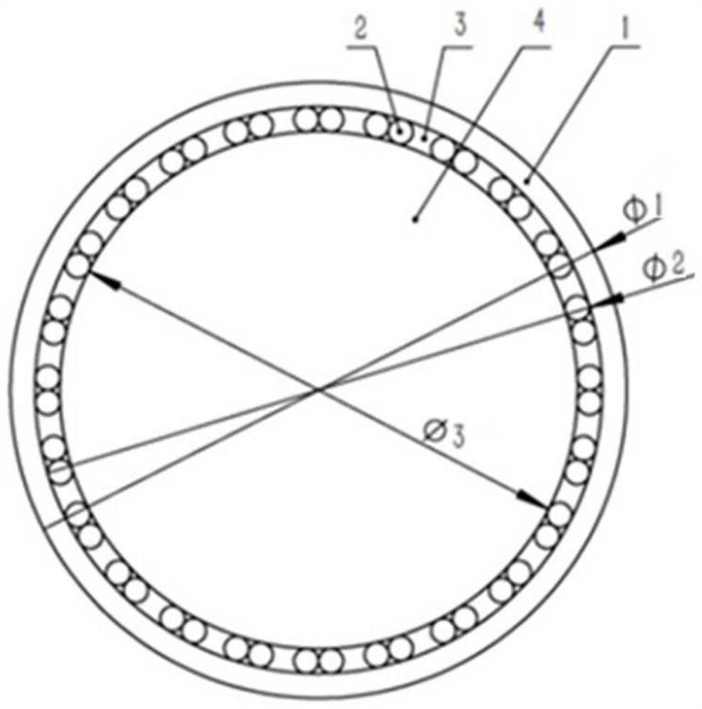
[0023] Refer to actual figure 1 , is a stress-free assembly method for optical elements of the present invention, characterized in that the method mainly includes an aluminum mirror frame 1, some polytetrafluoroethylene rods 2, molten silicone rubber 3 and optical elements 4;

[0024] The inner diameter of the aluminum mirror frame 1 is slightly larger than the diameter of the optical element 4 to be assembled and the sum of the diameters of the polytetrafluoroethylene rods 2, and the assembled optical element 4 is placed in the aluminum mirror frame 1, and then clings to the inner wall of the aluminum mirror frame 1 Evenly place several polytetrafluoroethylene rods 2 to support the optical element 4. The diameter of the polytetrafluoroethylene rod 2 is slightly smaller than the differe...


PUM

PropertyMeasurementUnit
Poisson's ratioaaaaaaaaaa

Abstract

A stress-free assembly method for large-diameter optical elements, comprising placing optical elements with assembly in an assembly frame; placing several polytetrafluoroethylene rods evenly between the assembly frame and the optical elements, and the inner diameter of the assembly frame is equal to the The sum of the diameter of the assembled optical element and the diameter of the polytetrafluoroethylene rod; pour molten filler into the gap between the assembly frame and the optical element until it is full; after the filler cools and solidifies, extract the polytetrafluoroethylene rod , the assembly is complete. The present invention is used for stress-free clamping and assembling of large-diameter optical elements. Compared with the traditional "sling type" and direct frame type two conventional clamping methods, it not only solves the stress concentration phenomenon of contact clamping caused by the self-weight of optical components, It also solves the problem of the stability of the mirror clamping.

Description

technical field [0001] The invention relates to an assembly method of optical elements, and is especially suitable for the field of assembly and adjustment of optical elements with large aperture, low deformation and high stability, and can realize very stable stress-free assembly and adjustment of optical elements. Background technique [0002] The stress-free assembly of optical components has always been a difficult problem in the field of optics, especially in the field of high-precision large-diameter optical components and large mirror optical detection. Meet the indicators, and poor stability. . Conventional optical component assembly is generally that skilled workers use special tools to embed optical components in the optical assembly frame based on experience, and point supports or slings and other fixtures to relieve contact stress and deformation. Under this assembly method, the distance between the optical component and the frame is Hard contact, when the opti...

Claims


Application Information

Patent Timeline
Patent Type & Authority Patents(China)
IPC IPC(8): G02B7/00
CPCG02B7/00
Inventor 顿爱欢嵇文超王东东张宝安吴福林徐学科
Owner SHANGHAI INST OF OPTICS & FINE MECHANICS CHINESE ACAD OF SCI
Features
  • R&D
  • Intellectual Property
  • Life Sciences
  • Materials
  • Tech Scout
  • Unparalleled Data Quality
  • Higher Quality Content
  • 60% Fewer Hallucinations
Learn More