Vehicle stabilizer and method for manufacturing said stabilizer

A manufacturing method and stabilizer technology, applied to vehicle springs, vehicle parts, springs/shock absorbers, etc., can solve problems such as increased component loads, inability to bear component loads, and detachment of restricting rings

Active Publication Date: 2019-10-29
NHK SPRING CO LTD
View PDF17 Cites 0 Cited by
  • Summary
  • Abstract
  • Description
  • Claims
  • Application Information

AI Technical Summary

Problems solved by technology

However, when the weight of the vehicle increases, the component load that moves the torque portion in the axial direction also increases
When the restraining ring is applied to a stabilizer mounted to a large vehicle, the restraining ring may come off and cannot bear the component load

Method used


Image

  • Vehicle stabilizer and method for manufacturing said stabilizer
  • Vehicle stabilizer and method for manufacturing said stabilizer
  • Vehicle stabilizer and method for manufacturing said stabilizer

Examples


Embodiment Construction

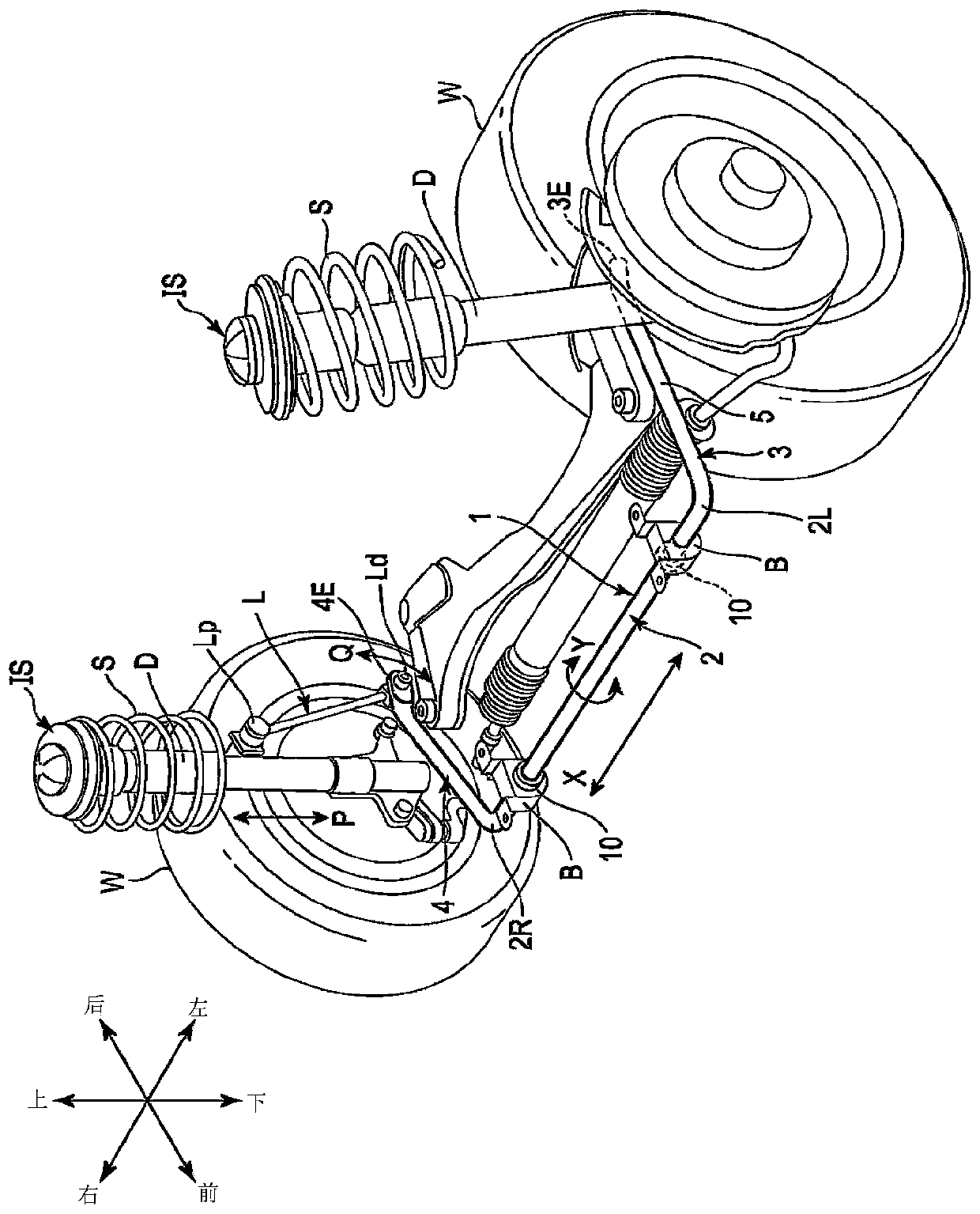
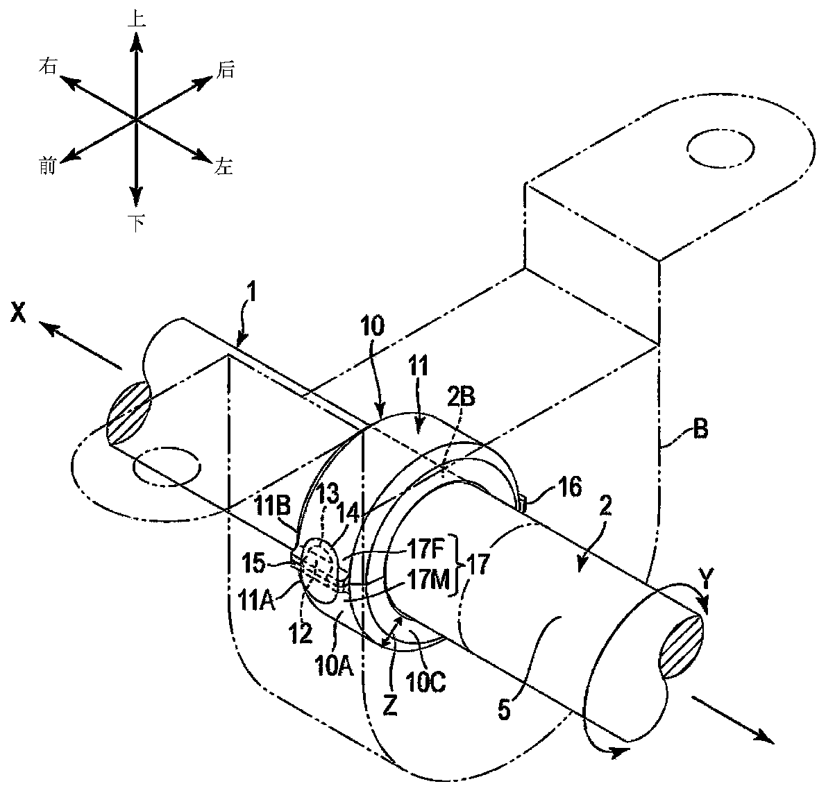
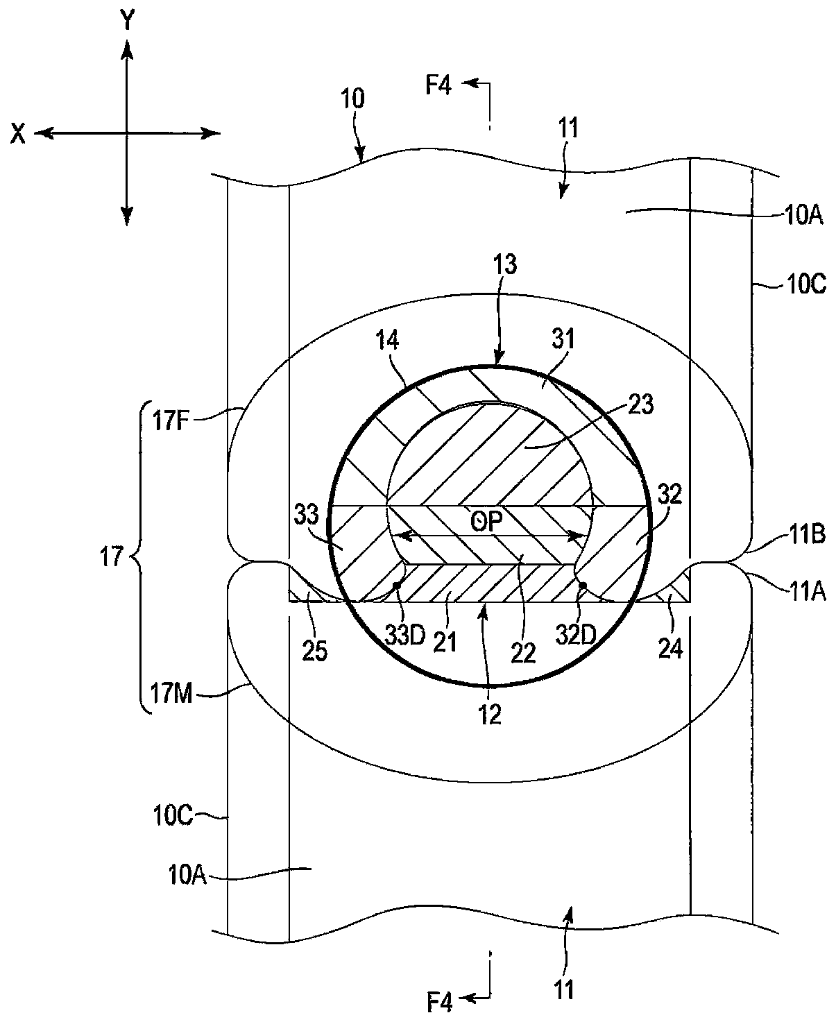
[0027] Below, refer to Figure 1 to Figure 14 A stabilizer 1 according to an embodiment of the present invention will be described. figure 1 An example perspective view of the stabilizer 1 mounted on a vehicle is shown. The stabilizer 1 is formed by bending a bar of spring steel into a U shape.

[0028] Examples of steel grades include SAE10B21, SAE15B26, SAE5160, etc. according to SAE, SUP9, etc., such as 26MnB5, 34MnB5, etc. according to JIS. The steel type of the stabilizer 1 is not limited to spring steel, and may also be high-strength steel or carbon-impregnated steel. The stabilizer 1 is covered with a coating film 5 such as epoxy resin containing a corrosion-resistant component.

[0029] The stabilizer 1 includes a torsion portion 2 , a pair of arm portions 3 and 4 , and a restraint ring 10 . The torsion portion 2 has a substantially linear shape and extends in the width direction (left-right direction) of the vehicle. A pair of arm portions 3 and 4 extend from bot...


PUM


Abstract

The present invention provides a stabilizer (1) equipped with a restriction ring (10) that can withstand a large component force load. The stabilizer (1) is provided with a restriction ring (10) connected to a torsion portion (2) at a connection portion (2B) adjacent to a bush (B). The restriction ring (10) has a body (11), a female portion (13), a male portion (12), and a welded portion (14). Thefemale portion (13) has a pair of gripping portions (32, 33) with a spacing therebetween decreasing in the direction away from a valley bottom portion (31). The male portion (12) has a neck portion (21), an expansion portion (22), and a contraction portion (23). The welded portion (14) covers at least the range of the contraction portion (23) and the valley bottom portion (31) and melts in the plate thickness direction (Z) from the outer peripheral surface (10A).

Description

technical field [0001] Embodiments of the present invention relate to a stabilizer for a vehicle, the stabilizer having a restricting ring for restricting movement in the axial direction, and a method for manufacturing the stabilizer. Background technique [0002] Vehicles such as automobiles are usually provided with stabilizers, which are used to link the suspension devices of the left and right wheels, in order to suppress the shaking of the vehicle body and improve driving stability. The stabilizer is a spring steel rod bent into a U shape, comprising a torque section suspended from the underside of the vehicle body by a cylindrical bushing, and a pair of arms attached to the stabilizer link of the suspension arrangement. [0003] When the vehicle turns, the spring of the suspension device on the outer wheel side is compressed by the centrifugal force, and the spring of the suspension device on the inner wheel side is extended. At this time, the arm portion attached to ...

Claims


Application Information

Patent Timeline
Patent Type & Authority Applications(China)
IPC IPC(8): B60G21/055F16B11/00
CPCB60G2202/135B60G2204/1222B60G2204/44B60G2206/427B60G2206/7102B60G2206/8208B60G2206/8209B60G2204/45B60G21/0551B60G2206/8201F16F1/16B23K2101/006F16B11/002B60G21/055F16B11/00B60G2204/41B60G2600/72B60G2206/8102
Inventor 仲村崇广勝野健治
Owner NHK SPRING CO LTD
Why Eureka
Try Eureka