
Water cup with temperature control function

A water cup and functional technology, applied in the field of water cups with temperature control function, can solve the problems of uneven cooling, slow cooling speed, long time consumption, etc., to avoid poor power connection or water inflow, uniform temperature rise and fall, and long service life Effect

Active Publication Date: 2019-11-01
礼何科技(上海)有限公司
View PDF5 Cites 4 Cited by
  • Summary
  • Abstract
  • Description
  • Claims
  • Application Information

AI Technical Summary

Problems solved by technology

[0002] Existing easy-to-carry water cups only have the function of heat preservation for temperature control. Through the inner liner material of the water cup and the tightness of the water cup, the water contained in the water cup can be kept warm, but the heat preservation effect is time-sensitive. Internal heat preservation, with the extension of time, the water temperature gradually drops, so that the heat preservation of the water cup has a time limit. The existing water cup with heating function uses the power connection port to connect to the external power supply, which is the heating device in the water cup. Provide electric energy to heat the water in the water cup. This kind of water cup needs a specific power-on interface and power-on environment before it can be used, which makes the water cup have limitations in use. In addition, the external power-on interface is easy to be wet by water, causing leakage And other unsafe issues, during the heating process, the water cup is in a prohibited state, causing inconvenience to use
[0003] Secondly, when cooling the water contained in the water cup, the cup lid is usually opened to cool naturally. The cooling speed of this method is slow and takes a long time, and the upper layer of water in contact with the air is cooled first, making the cooling uneven. A cooling method is to cool the water contained in the water cup through a stirring rod. Manual operation is time-consuming and laborious, and the usability is poor.

Method used


Image

  • Water cup with temperature control function
  • Water cup with temperature control function
  • Water cup with temperature control function

Examples


Embodiment Construction

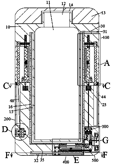
[0020] Combine below Figure 1-8 The present invention is described in detail, and for convenience of description, the orientations mentioned below are now stipulated as follows: the up and down directions mentioned below are related to figure 1 The up and down directions of the projection relationship are the same.

[0021] refer to Figure 1-8According to an embodiment of the present invention, a water cup with a temperature control function includes a water cup 10, a water storage chamber 11 is provided inside the water cup 10, and a cup opening 12 is provided on the upper side of the water storage chamber 11 to communicate with the external space , the upper side of the water cup 10 is provided with a cup cover 13, the inside of the cup cover 13 is provided with a sealing groove 14 with the opening facing downward, the sealing groove 14 is threadedly sealed with the water cup 10, and the outer side of the water storage chamber 11 is provided There is a U-shaped temperatu...


PUM


Abstract

The invention discloses a water cup with a temperature control function. The water cup comprises a water cup body; a water storage cavity is formed in the water cup body; a U-shaped temperature control cavity is formed in the outer side of the water storage cavity; a heating plate is fixedly arranged on the inner end wall of the temperature control cavity; a solar panel is fixedly arranged at oneend, close to the water storage cavity, of a rotating plate; a photovoltaic controller is electrically connected with one end, far away from the water storage cavity, of the solar panel; and the photovoltaic controller is electrically connected with a storage battery through a conductive wire. According to the water cup, solar energy is converted into electric energy to be stored in the storage battery; a temperature control power source of the water cup is not limited by regions and environments; water in the water storage cavity is uniformly heated and cooled; and the water cup is long in service life, portable and stable.

Description

technical field [0001] The invention relates to the technical field of daily necessities, in particular to a water cup with a temperature control function. Background technique [0002] Existing easy-to-carry water cups only have the function of heat preservation for temperature control. Through the inner liner material of the water cup and the tightness of the water cup, the water contained in the water cup can be kept warm, but the heat preservation effect is time-sensitive. Internal heat preservation, with the extension of time, the water temperature gradually drops, so that the heat preservation of the water cup has a time limit. The existing water cup with heating function uses the power connection port to connect to the external power supply, which is the heating device in the water cup. Provide electric energy to heat the water in the water cup. This kind of water cup needs a specific power-on interface and power-on environment before it can be used, which makes the w...

Claims


Application Information

Patent Timeline
Patent Type & Authority Applications(China)
IPC IPC(8): A47G19/22
CPCA47G19/2288
Inventor 叶梦
Owner 礼何科技(上海)有限公司
Features
  • Generate Ideas
  • Intellectual Property
  • Life Sciences
  • Materials
  • Tech Scout
  • Unparalleled Data Quality
  • Higher Quality Content
  • 60% Fewer Hallucinations
Learn More