
Scalpel for thoracic surgery

A scalpel and thoracic surgery technology, applied in the field of surgical tools, can solve the problem of single function of the scalpel, achieve good application prospects and ensure cleanliness

Pending Publication Date: 2019-11-01
SHENZHEN POLYTECHNIC
View PDF0 Cites 0 Cited by
  • Summary
  • Abstract
  • Description
  • Claims
  • Application Information

AI Technical Summary

Problems solved by technology

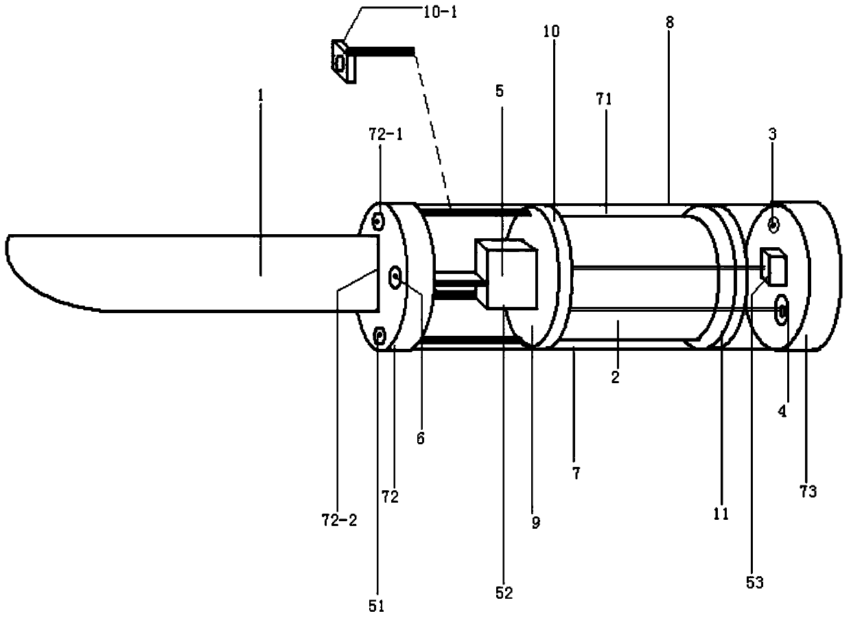
[0004] In order to overcome the shortcomings of the existing scalpels used in thoracic surgery, which have single functions and cannot provide more functions for surgeons, as well as the limitations of existing surgical lighting and video recording, the present invention provides a surgical knife that can be easily replaced. The blade body has a miniature camera and a lighting lamp inside the fixed barrel of the scalpel, and is equipped with a replaceable plastic isolation shell on the outside of the fixed barrel of the scalpel, which ensures the cleanliness of the operation. Turn off the lighting to provide better lighting without dead angle for the operation process. The micro camera can be close to the surgical site during the whole operation process, and can record every operation point in the operation without dead angle. Follow-up surgeons, management departments and patients When the video of the existing operating room cannot be obtained from the effective video of the surgical site, the video information stored in the micro-camera can be used to effectively grasp the surgical process of the surgical site, which brings convenience to the operator and also improves the management. A scalpel for thoracic surgery that provides more technical support for departments and patients to query surgical video information

Method used


Image

  • Scalpel for thoracic surgery
  • Scalpel for thoracic surgery
  • Scalpel for thoracic surgery

Examples


Embodiment Construction

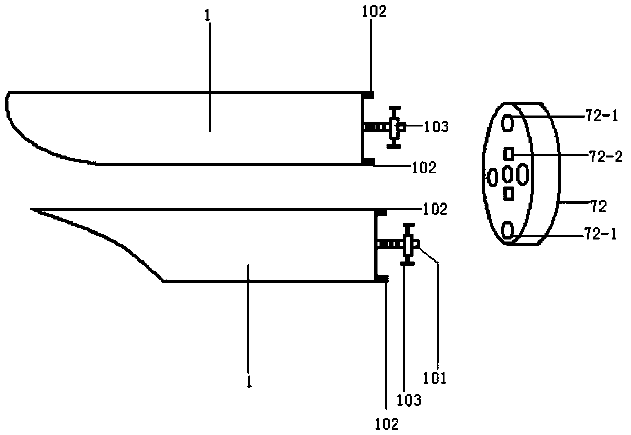
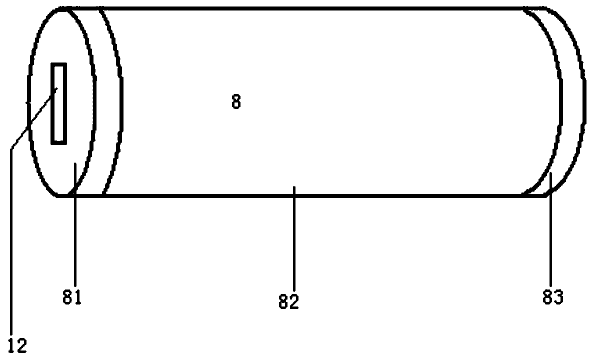
[0020] figure 1 , 2 , 3, a scalpel for thoracic surgery, including a surgical blade body 1 with various shapes and various functions, a lithium battery 2, a power switch 3, a charging socket 4, a miniature camera 5 with a split camera, a light-emitting Diode 6 also has scalpel fixing tube 7, plastic isolation shell 8, light control circuit 9, there is an externally threaded rod 101 in the middle part of the right side end of scalpel body 1, and the upper and lower parts of the right side end of scalpel body 1 each have a Root limit rod 102, external threaded rod 101 is equipped with a manual locking nut 103, and scalpel fixed cylinder 7 comprises the cylinder body 71 that external thread interior is hollow structure, cylinder body cover 72, rear cover 73 that left and right ends outside, The inside of the cylinder cover 71 and the rear cover 73 have internal threads (the outer end is a closed structure), and the left end of the ring cylinder cover 72 has four openings 72-1, a...


PUM


Abstract

A scalpel for thoracic surgery comprises a scalpel blade body, a lithium storage battery, a power switch, a charging socket, a camera, a light-emitting diode as well as comprises a scalpel fixing drum, a plastic isolation casing and a light-operated circuit; the scalpel fixing drum comprises a drum body, a drum lid and a back lid; the lithium storage battery, the power switch, the charging socket,the camera, the light-emitting diode and the light-operated circuit are mounted in the drum body and connected through leads; the drum lid and the back lid are mounted at left and right ends of the drum body respectively; the scalpel blade body is mounted at the left end of the drum lid; and the plastic isolation casing is mounted on the outer side of the scalpel fixing drum. The scalpel can provide better lighting without dead corners for the surgery process, the camera can perform video recording without dead corner for each surgery point in the surgery, an operator, an administration department and a patient can effectively master the surgery process of the surgery part by consulting video information stored in a mini-camera, convenience is brought to the operator, and more technical support can be provided for the administration department and the patient.

Description

technical field [0001] The invention relates to the field of surgical tools, in particular to a scalpel for thoracic surgery. Background technique [0002] Including thoracic surgery, various scalpels with different shapes and functions are indispensable tools. Existing surgical knives only have the function of cutting the affected part, and have the disadvantage of single function. In the actual operation of surgery, although the surgical shadowless lamp can provide lighting, and the surgical coordinators can also provide lighting when necessary, but due to the operator's surgical angle and the location of the patient's surgical site, it is not possible to effectively ensure the effective lighting of the surgical site. (e.g. inside the abdominal cavity at the surgical site). [0003] The existence of doctor-patient disputes in clinical medicine has exacerbated the distrust between doctors and patients, which is not conducive to improving the enthusiasm of doctors for medi...

Claims


Application Information

Patent Timeline
Patent Type & Authority Applications(China)
IPC IPC(8): A61B17/3211A61B90/00A61B90/30
CPCA61B17/3211A61B90/361A61B90/30A61B2090/309
Inventor 罗滨
Owner SHENZHEN POLYTECHNIC
Learn More