Battery pack

A battery and package technology, applied in the direction of batteries, electric power devices, battery pack components, etc., can solve the problems of higher position, loading, and increased thickness of the fuel cell system box in the upper and lower directions, and achieve small size in the height direction, Achieve lightweight effect

Pending Publication Date: 2019-11-01
HONDA MOTOR CO LTD
View PDF8 Cites 6 Cited by
  • Summary
  • Abstract
  • Description
  • Claims
  • Application Information

AI Technical Summary

Problems solved by technology

[0007] In addition, in the above-mentioned conventional technology, since the end of the fuel cell is supported on the upper surface of the stack frame, the position of the upper surface of the fuel cell may become higher, and the thickness of the fuel cell system case in the vertical direction may increase, making it difficult to move to the upper surface of the stack frame. Carrying under the floor of the vehicle

Method used


Image

  • Battery pack
  • Battery pack
  • Battery pack

Examples


no. 1 approach

[0037] Below, based on Figure 1 to Figure 5 The first embodiment of the present invention will be described.

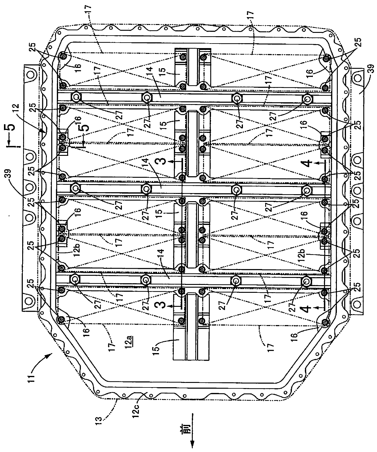
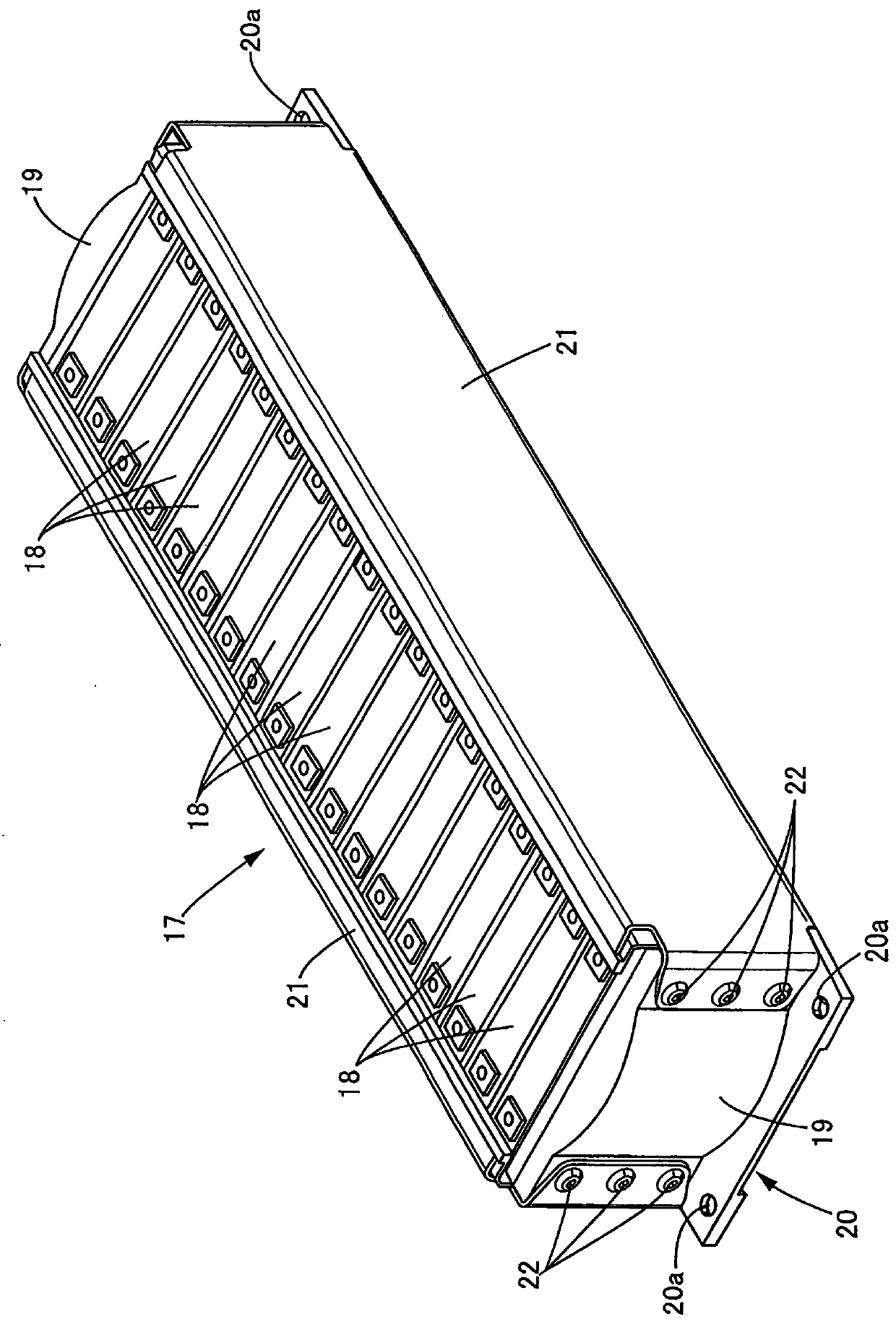
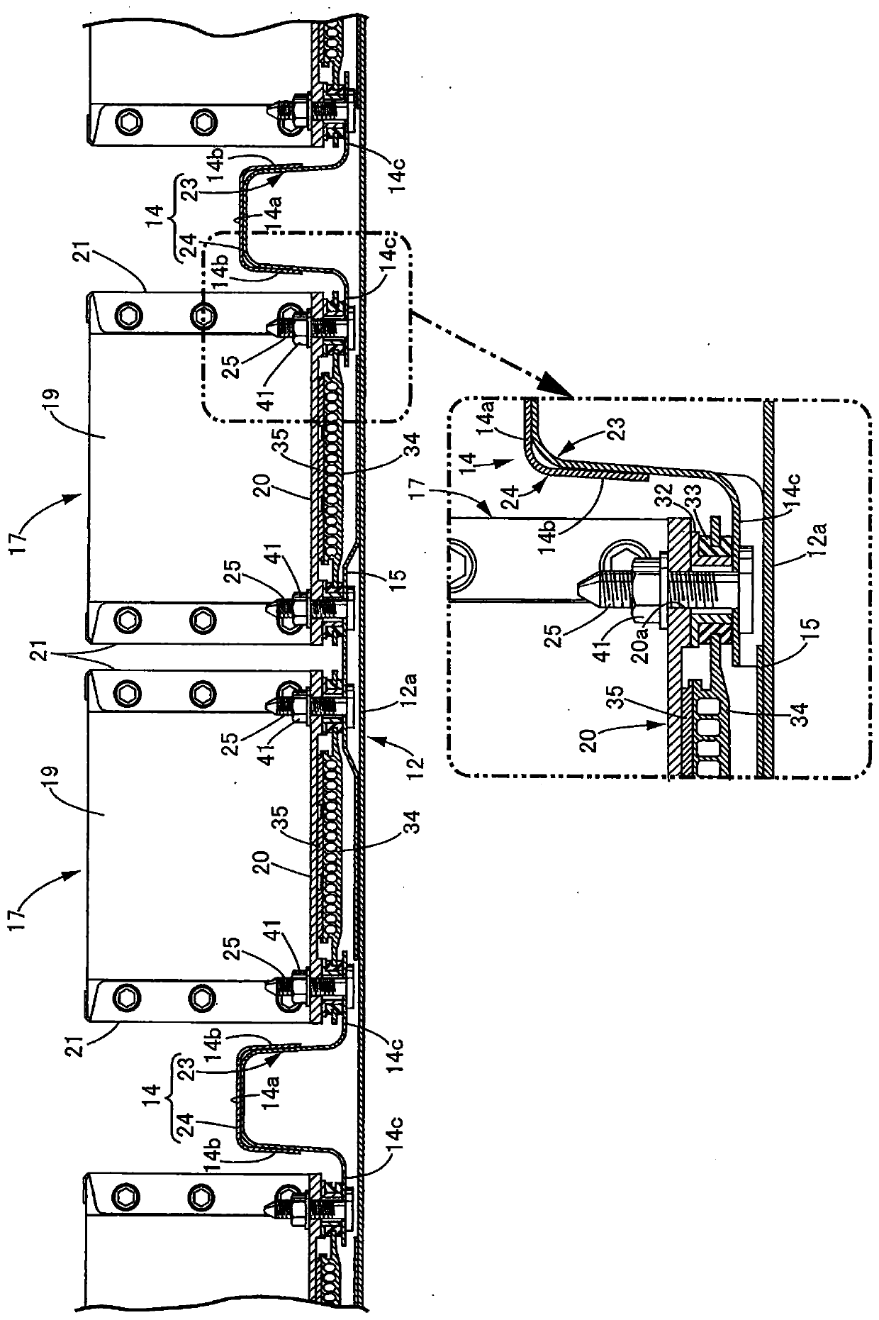
[0038] Such as figure 1 As shown, a battery pack 11 installed under the floor of an electric vehicle includes a container-shaped case 12 whose upper surface is open, and a cover 13 that closes the upper surface opening of the case 12 . On the bottom wall 12a of the casing 12, three cross beams 14... are provided at predetermined intervals in the front-rear direction and extend along the vehicle width direction, and are arranged on the center line of the casing 12 so as to be perpendicular to the three cross beams 14... The vertical frame 15 ... extended along the front-back direction is provided in the manner. The vertical frame 15... is divided into four parts at the position which intersects with three beams 14.... In addition, four support brackets 16 . In addition, 12 rectangular parallelepiped battery modules 17... are supported on the upper surfaces of the ...

no. 2 approach

[0054] Next, based on Figure 6 A second embodiment of the present invention will be described.

[0055] In the first embodiment, when the battery modules 17 ... are mounted on the case 12 of the battery pack 11, the direction in which the cells are stacked is along the vehicle width direction. However, in the second embodiment, the direction in which the cells are stacked is along the forward and backward direction. That is, the two front bolt holes 20a, 20a of each battery module 17 are supported by the flange 14c of the front beam 14, and the two rear bolt holes 20a, 20a are supported by the flange 14c of the rear beam 14. . Therefore, according to this embodiment, the stud bolts 25... of the support bracket 16... and the stud bolts 25... of the vertical frame 15 of 1st Embodiment are unnecessary.

[0056] According to this embodiment as well, it is possible to achieve the same effect as that of the first embodiment.


PUM


Abstract

It is an object of the invention to reduce the dimension in the up-down direction of a battery pack housing a battery of an electric vehicle. In a battery pack, a battery driving an electric vehicle is housed inside a case. A skeleton member extending in a vehicle width direction is provided on a bottom wall of the case. The skeleton member has a hat-shaped section having an upper wall, paired side walls, and paired flanges and opening downwardly. The flange is fixed to the bottom wall. Part of the battery is supported on an upper face of the flange. Therefore, by supporting the battery by utilizing the skeleton member reinforcing the case against the impact of a side collision, it is possible to make a special battery support member unnecessary and achieve small size and light weight of the battery pack, and also to reduce the dimension in the height direction of the battery pack compared with a case where part of a battery is supported on an upper face of a skeleton member.

Description

technical field [0001] The present invention relates to a battery package in which a battery for driving an electric vehicle is accommodated inside a case. Background technique [0002] According to the following Patent Document 1, it is known that the bottom wall of the fuel cell system box is provided with a top-hat-shaped front stack frame and a rear stack frame extending along the vehicle width direction, and the front and rear stack frames of the fuel cell are connected to each other. Both ends are supported by the upper surfaces of the front stack frame and the rear stack frame. [0003] prior art literature [0004] patent documents [0005] Patent Document 1: Japanese Patent Laid-Open No. 2006-176105 [0006] The problem to be solved by the invention [0007] In addition, in the above-mentioned conventional technology, since the end of the fuel cell is supported on the upper surface of the stack frame, the position of the upper surface of the fuel cell may become...

Claims


Application Information

Patent Timeline
Patent Type & Authority Applications(China)
IPC IPC(8): B60K1/04H01M50/209
CPCB60K1/04H01M50/209B60K2001/0438Y02T10/70Y02T90/14Y02T10/7072Y02E60/10B60K2001/0405B60R16/04B62D21/157H01M2220/20
Inventor 小泽裕之筱田龙
Owner HONDA MOTOR CO LTD
Why Eureka
Try Eureka