Variable nozzle for turbocharger and control method of variable nozzle as well as turbocharger

A turbocharger and nozzle technology, which is applied to machines/engines, stators, engine components, etc., can solve the problems of high failure rate or failure rate, not popularized, complex mechanical structure, etc., to achieve cost and failure rate reduction, Simple structure and reduced risk of failure

Inactive Publication Date: 2019-11-01
奕森科技(上海)有限公司
View PDF5 Cites 9 Cited by
  • Summary
  • Abstract
  • Description
  • Claims
  • Application Information

AI Technical Summary

Problems solved by technology

For example, variable vane nozzles with rotatable vanes generally have good aerodynamic performance, but are mechanically complex and have a high rate of failure or failure due to the high number of moving parts
Although the sliding piston type variable noz

Method used


Image

  • Variable nozzle for turbocharger and control method of variable nozzle as well as turbocharger
  • Variable nozzle for turbocharger and control method of variable nozzle as well as turbocharger
  • Variable nozzle for turbocharger and control method of variable nozzle as well as turbocharger

Examples


Embodiment Construction

[0061] The following examples of the present invention are described in detail below. The following examples are implemented on the premise of the technical solution of the present invention, and detailed implementation methods and specific operating procedures are provided, but the protection scope of the present invention is not limited to the following the embodiment.

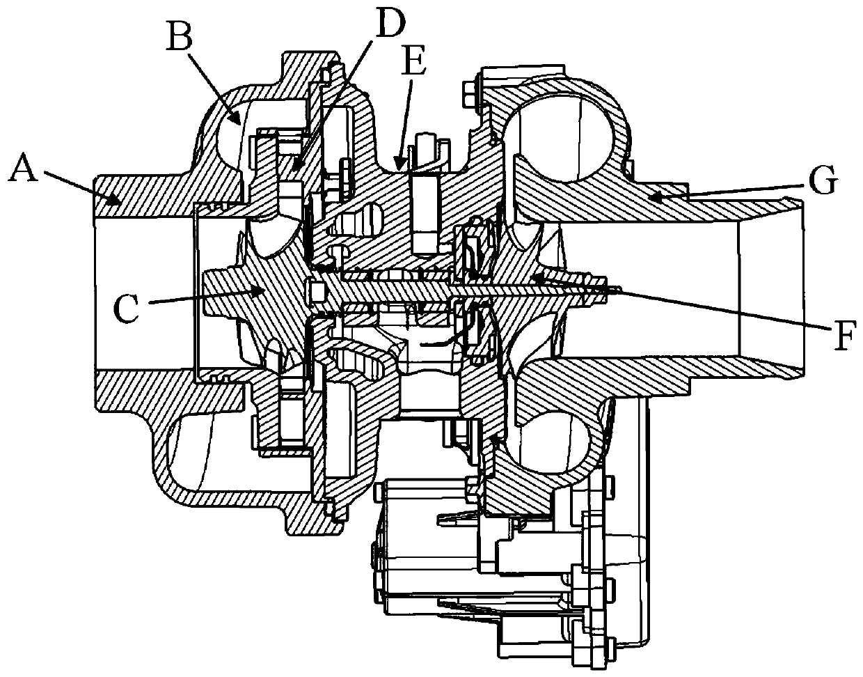
[0062] figure 1 It is a schematic cross-sectional structure diagram of a typical variable nozzle turbocharger. Wherein, the volute A includes a volute channel B, and the volute channel B is an annular cavity surrounding the turbine C for collecting exhaust gas from the engine and using the exhaust gas to drive the turbine C to rotate. The turbine C driven by the exhaust gas drives the coaxial pressure wheel F to rotate in the pressure shell G, and compresses the air collected in the pressure shell G to provide boost pressure for the engine intake. The pressure and density of the compressed air increase, bu...


PUM


Abstract

The invention provides a variable nozzle for a turbocharger and a control method of the variable nozzle as well as a turbocharger. The variable nozzle comprises a nozzle ring, an opening ring and a cover plate; and the advantages of a variable blade type nozzle and a sliding piston type nozzle in the prior art are integrated through a feasible design structure, the pneumatic performance is good, the application temperature range is wide, the structure is simple, the production cost is low and the control is easy to realize.

Description

technical field [0001] The invention belongs to the field of turbochargers, in particular to a variable nozzle for a turbocharger and a control method thereof, and a turbocharger with the variable nozzle. Background technique [0002] A turbocharger is a device used in conjunction with an internal combustion engine to compress air delivered to the engine intake so that it is thoroughly mixed with fuel and combusted in the engine to increase the engine's power output. A turbocharger includes a compressor wheel mounted in a compressor housing and a turbine wheel mounted in a turbine housing. Wherein, the turbine casing is formed separately from the compressor casing, and there is another intermediate casing connected between the turbine casing and the compressor casing for installation of bearings and cooling and lubrication. The turbine casing defines a substantially annular flow channel surrounding the turbine, exhaust gas enters the flow channel from the engine and blows t...

Claims


Application Information

Patent Timeline
IPC IPC(8): F02B37/22F02B37/24F02B39/00F01D9/04F01D17/16F01D25/00
CPCF01D9/041F01D17/165F01D25/00F02B37/22F02B37/24F02B39/00Y02T10/12
Inventor 顾茸蕾朱明明刘伟吴孟龙
Owner 奕森科技(上海)有限公司
Why Eureka
Try Eureka