[0024] The present invention will be described in further detail below in conjunction with the accompanying drawings and specific embodiments, but the protection scope of the present invention is not limited thereby.
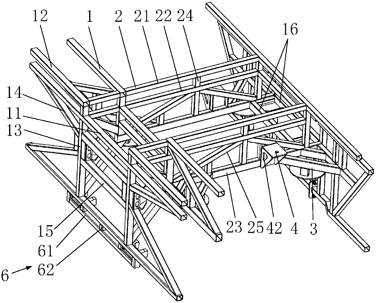
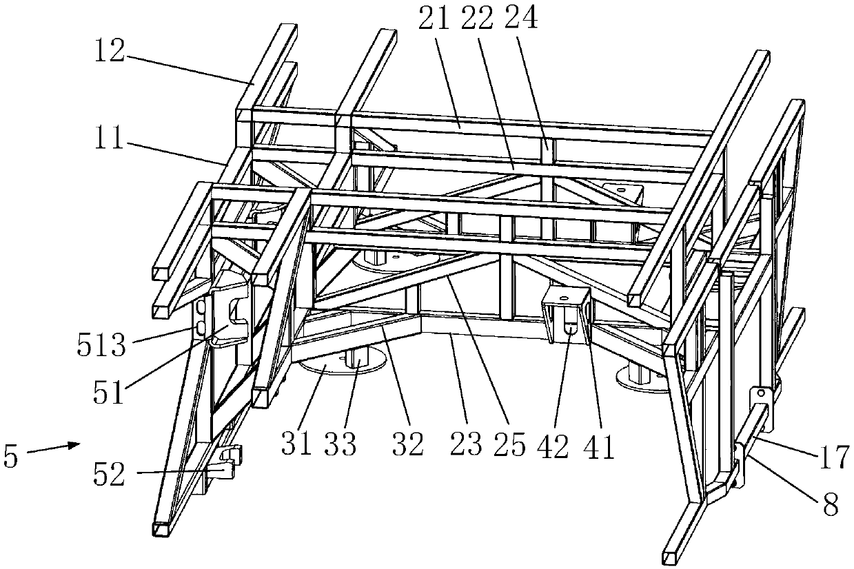
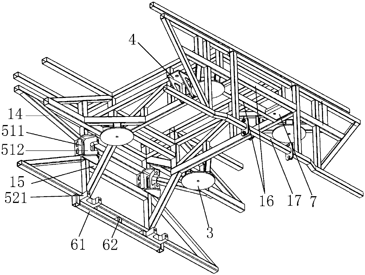
[0025] like figure 1 and figure 2 As shown, the rear axle frame for passenger cars in this embodiment includes a suspension system installation assembly, a beam assembly 1 and two sets of longitudinal beam assemblies 2 . Among them, the beam assembly 1 and the longitudinal beam assembly 2 are arranged in a criss-cross pattern; the beam assembly 1 includes a middle beam 11 and a side beam 12, the middle beam 11 is arranged between adjacent longitudinal beam assemblies 2, and the side beam 12 is arranged between the longitudinal beam assembly 2 and the side beam 12. Between the side walls of the passenger car. In this embodiment, the suspension system installation assembly includes four groups of airbag installation parts 3, and each group of airbag installation parts 3 is installed between the side beam 12 and the longitudinal beam assembly 2, wherein two groups of airbag installation parts 3 are installed with the other two groups of airbags. The parts 3 are arranged symmetrically along the center line of the stringer assembly 2 .
[0026] The present invention is provided with four sets of airbag installation parts 3, and each airbag installation part 3 is installed between the side beam 12 and the side beam assembly 2, which makes the active force of each airbag installation part 3 pass through the side beam assembly 2, side beam 12 Effectively transmit the force to the bus body, thereby effectively distributing the borne force to the various parts of the car body, avoiding the problem of stress concentration at the installation part of the airbag installation part 3 during the operation of the bus, effectively improving the safety and reliability of the bus operation, and the bus The service life is high; at the same time, the two sets of airbag mounting parts 3 and the other two sets of airbag mounting parts 3 are arranged symmetrically along the center line of the stringer assembly 2, and the airbag mounting parts 3 are evenly arranged to effectively slow down the vertical force transmitted by the airbag. It has a reasonable layout and is easy to assemble.
[0027] like figure 1 As shown, the airbag installation part 3 includes a circular airbag cover plate 31 , horizontal braces 32 and airbag uprights 33 . Wherein, both ends of the horizontal brace 32 are connected to the side beam 12 and the longitudinal beam assembly 2 , and the circular airbag cover 31 is arranged under the horizontal brace 32 through the airbag column 33 . The air bag installation structure has high reliability, avoids air bag installation failure, and has a simple structure. Further, the diameter of the circular airbag cover plate 31 in this embodiment is larger than the diameter of the airbag when the airbag is full, so that the edge of the airbag does not leak when the airbag is full, ensuring the safety of the airbag during operation.
[0028] like figure 1 and figure 2 As shown, the suspension system installation assembly of this embodiment further includes two shock absorber brackets 4 , and each shock absorber bracket 4 is installed on the outer side of the longitudinal beam assembly 2 . It enables the active force of the shock absorber bracket 4 to be effectively transmitted to the bus body through the longitudinal beam assembly 2 and the side beam 12, thereby effectively distributing the borne force to various parts of the vehicle body, and avoiding the shock absorber bracket 4 from running on the bus. The problem of stress concentration in the installation part during the process. Meanwhile, the shock absorber bracket 4 is arranged symmetrically along the center line of the longitudinal beam assembly 2 . The utility model has the advantages of reasonable layout, good aesthetics and convenient assembly.
[0029] Further, the longitudinal beam assembly 2 includes an upper longitudinal beam 21 , a middle longitudinal beam 22 , a lower longitudinal beam 23 , a longitudinal beam reinforcing column 24 and a longitudinal brace 25 . Among them, the upper longitudinal beam 21, the middle longitudinal beam 22 and the lower longitudinal beam 23 are arranged sequentially from top to bottom; Between; the two ends of the longitudinal brace 25 are respectively connected to the intersection of the middle longitudinal beam 22 and the longitudinal beam reinforcing column 24, and the intersection of the lower longitudinal beam 23 and the longitudinal beam reinforcing column 24. It has reasonable structure, good structural strength and stability. In this embodiment, the shock absorber bracket 4 is installed on the longitudinal brace 25 and the lower longitudinal beam 23, which effectively ensures the installation reliability of the shock absorber bracket 4 and effectively alleviates the impact force transmitted by the shock absorber. In this embodiment, the shock absorber bracket 4 is welded to the longitudinal brace 25 and the lower longitudinal beam 23 .
[0030] Further, the shock absorber bracket 4 is an L-shaped bracket. The two ends of the L-shaped support are provided with reinforcing ribs 41, and the reinforcing ribs 41 are welded and fixed with the L-shaped support. The arrangement of the reinforcing ribs 41 enhances the strength of the shock absorber support 4. Both the L-shaped bracket and the reinforcing rib 41 are provided with a first weight-reducing hole 42 , which satisfies the requirement of reducing the weight of the vehicle while meeting the strength requirement of the shock absorber bracket 4 . In this embodiment, the first lightening hole 42 on the rib 41 is a triangular lightening hole. The first lightening hole 42 on the L-shaped bracket is a waist-shaped lightening hole.
[0031] like figure 1As shown, the suspension system installation assembly also includes a thrust rod bracket 5, and the thrust rod bracket 5 is arranged near the middle section of the vehicle frame. The thrust rod bracket 5 includes two upper thrust rod brackets 51 , and the two upper thrust rod brackets 51 are arranged symmetrically along the center line of the longitudinal beam assembly 2 . The utility model has the advantages of reasonable layout, good aesthetics and convenient assembly. In this embodiment, the crossbeam assembly 1 further includes a crossbeam reinforcement column 13 , a transverse brace 14 and a thrust rod reinforcement crossbeam 15 . Among them, the crossbeam reinforcement column 13 is supported at the junction of the crossbeam assembly 1 and the longitudinal beam assembly 2; the lateral diagonal brace 14 is connected between the side beam 12 and the crossbeam reinforcement column 13; the thrust rod reinforcement beam 15 is arranged between the middle beams 11, In addition, both ends of the thrust rod reinforcing beam 15 are respectively connected to the corresponding side beam reinforcing columns 13 . The upper thrust rod bracket 51 is installed on the beam reinforcement column 13 , and the upper thrust rod bracket 51 is located between the thrust rod reinforcement beams 15 . Its structural stability is good, and the installation reliability and strength requirements of the upper thrust rod bracket 51 are guaranteed, and the occurrence of installation failure of the upper thrust rod bracket 51 is avoided.
[0032] In this embodiment, the thrust rod bracket 5 further includes two lower thrust rod brackets 52 . The two lower thrust rod brackets 52 are arranged symmetrically along the center line of the longitudinal beam assembly 2, and the layout is reasonable and the appearance is good. In this embodiment, the bottom of the beam assembly 1 is provided with an installation assembly 6, the installation assembly 6 includes an installation beam 61 and a plurality of installation columns 62, and a plurality of installation columns 62 are arranged between the installation beam 61 and the beam assembly 1 to form a closed installation framework. The lower thrust rod bracket 52 is installed in the mounting frame. Its structure is stable, effectively ensuring the installation reliability and strength requirements of the lower thrust rod bracket 52 .
[0033] Further, the upper thrust rod bracket 51 of this embodiment includes a U-shaped mounting plate 511 and an upper thrust rod connecting piece 512 . Among them, the U-shaped mounting plate 511 is provided with a plug welding hole 513. When the upper thrust rod bracket 51 is welded with the beam reinforcement column 13, in addition to the full welding of the connection position, the plug welding hole 513 needs to be fully welded to ensure that the upper thrust rod The connection strength of the bracket 51; the upper thrust rod connector 512 is welded in the U-shaped mounting plate 511 for connecting with the upper thrust rod. Its structure is simple, and the upper thrust rod is easy to install and has high reliability. In this embodiment, the upper thrust rod connecting piece 512 is a casting; the U-shaped mounting plate 511 is a steel plate with a thickness of 8 mm.
[0034] Further, the lower thrust rod bracket 52 of this embodiment includes a lower thrust rod connecting piece 521 . The lower thrust rod connecting part 521 is clamped in the installation frame for connecting with the lower thrust rod. Its structure is simple, and the lower thrust rod is easy to install and has high reliability. At the same time, the lower thrust rod connecting piece 521 is welded and fixed in the installation frame, which ensures the connection strength of the lower thrust rod bracket 52 . The back side of the lower thrust rod connector 521 is provided with a second weight-reducing hole. The setting of the second weight-reducing hole not only meets the strength requirement of the lower thrust rod bracket 52, but also ensures the requirement of vehicle weight reduction. In this embodiment, the lower thrust rod connecting piece 521 is a casting.
[0035] like image 3 As shown, the suspension system installation assembly also includes two stabilizer bar boom brackets 7 . The two stabilizer bar hanger brackets 7 are arranged close to the rear section of the vehicle frame, and symmetrically arranged along the center line of the longitudinal beam assembly 2, which has a reasonable layout and good aesthetics. In this embodiment, the beam assembly 1 further includes two boom beams 16, one of which is connected between the two longitudinal beam assemblies 2, and the other boom beam 16 is arranged on the middle beam 11 near the rear frame. Between them, the stabilizer bar suspender bracket 7 is installed between the two suspender beams 16 . Its structure is stable, which effectively guarantees the installation reliability and strength requirements of the stabilizer bar boom bracket 7 .
[0036] Further, the stabilizer rod bracket 7 of this embodiment is a U-shaped bracket. The two ends of the U-shaped bracket are respectively welded to the suspender beam 16 on the corresponding side, which further ensures the installation stability of the U-shaped bracket and avoids the occurrence of installation failure.
[0037] like figure 2 As shown, the beam assembly 1 also includes a movable beam 17 . An installation gap 8 is provided on the middle beam 11 located near the rear frame and at the bottom of the frame; the movable beam 17 is detachably installed in the installation gap 8 through fasteners. In order to facilitate the installation and disassembly of the vehicle transmission shaft, the disassembly and installation efficiency of the transmission shaft is improved.
[0038] Further, the movable beam 17 in this embodiment is a protruding structure protruding toward the rear frame. It enables the movable beam 17 to match different types of bridge structures, and has strong versatility.
[0039] In this embodiment, the circular airbag cover plate 31, the shock absorber bracket 4, and the stabilizer bar boom bracket 7 all adopt steel plates with a thickness of 6 mm; the upper thrust rod bracket 51 and the lower thrust rod bracket 52 adopt a casting structure to ensure Suspension system installation components have sufficient strength to avoid installation failure when the vehicle is running.
[0040] While the invention has been described with reference to a preferred embodiment, various modifications may be made and equivalents may be substituted for parts thereof without departing from the scope of the invention. In particular, as long as there is no structural conflict, the technical features mentioned in the various embodiments can be combined in any manner. The present invention is not limited to the specific embodiments disclosed herein, but includes all technical solutions falling within the scope of the claims.