Floating continuous crawler-type water surface oil absorption device

A crawler-type, oil-absorbing sponge technology, which is used in grease/oily substance/float removal devices, general water supply conservation, and open-air water surface cleaning, etc. The effect of reduced resource recovery, fast oil absorption, and high oil absorption rate

Pending Publication Date: 2019-11-05
郭屹珉
View PDF0 Cites 1 Cited by
  • Summary
  • Abstract
  • Description
  • Claims
  • Application Information

AI Technical Summary

Problems solved by technology

The existing property method treatment device has the disadvantages of being too simple, unable to operate continuously, low oil absorption rate, slow oil absorption speed,

Method used


Image

  • Floating continuous crawler-type water surface oil absorption device
  • Floating continuous crawler-type water surface oil absorption device

Examples


Example Embodiment

[0024] Example 1

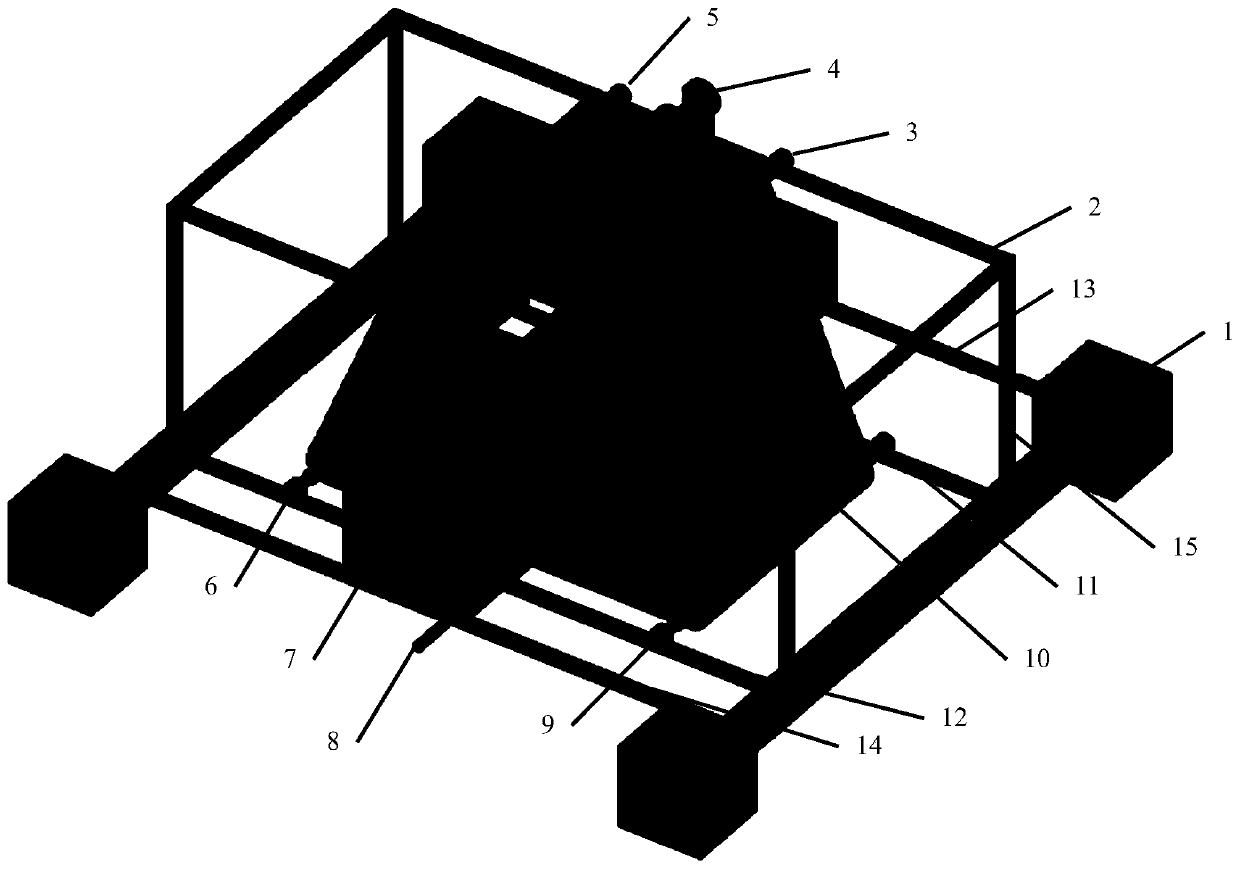
[0025] As shown in the figure, the floating continuous crawler water surface oil absorbing device of the present invention includes two left and right elongated hollow floats 1, a rectangular frame 2, an upper right active roller 3, a counter-rolling roller 4, an upper left active roller 5, Lower left driven roller 6, oil tank 7, lower right driven roller 9, crawler-type oil-absorbing sponge 10, driven roller support bar 11 / 12, oil tank support bar 13 / 14, and rectangular frame support bar 15, through which the rectangular frame passes Four rectangular frame support rods 15 are fixed on two long hollow floats, the upper right active roller 3 and the upper left active roller 5 are fixedly arranged on the long side frame of the rectangular frame 2, and the upper right active roller 3 and the upper left active roller Between the rollers 5 are fixedly arranged a pair of rollers 4 that squeeze the crawler-type oil-absorbing sponge, and between the two long hollow flo...

Example Embodiment

[0026] Example 2

[0027] As shown in the figure, the floating continuous crawler water surface oil absorbing device of the present invention includes two left and right elongated hollow floats 1, a rectangular frame 2, an upper right active roller 3, a counter-rolling roller 4, an upper left active roller 5, Lower left driven roller 6, oil tank 7, lower right driven roller 9, crawler-type oil-absorbing sponge 10, driven roller support bar 11 / 12, oil tank support bar 13 / 14, and rectangular frame support bar 15, through which the rectangular frame passes Four rectangular frame support rods 15 are fixed on two long hollow floats, the upper right active roller 3 and the upper left active roller 5 are fixedly arranged on the long side frame of the rectangular frame 2, and the upper right active roller 3 and the upper left active roller Between the rollers 5 are fixedly arranged a pair of rollers 4 that squeeze the crawler-type oil-absorbing sponge, and between the two long hollow flo...


PUM


Abstract

The invention discloses a floating continuous crawler-type water surface oil absorption device. The device floats on the water surface, can automatically and continuously absorb oil on the water surface, and is simple and convenient to operate. The device comprises two long hollow buoys, a rectangular frame, an upper right driving roller, a rolling roller, an upper left driving roller, a lower left driven roller, an oil tank, a lower right driven roller, a crawler-type oil absorption sponge, driven roller supporting cross rods, oil tank supporting cross rods and a rectangular framework supporting rod. The rectangular framework is fixed to the buoys through the supporting rods, the upper right driving roller and the upper left driving roller are fixed to the framework, the rolling roller for extruding the crawler-type oil absorption sponge is arranged, and the two driven roller supporting cross rods and the two oil tank supporting cross rods are arranged between the two long hollow buoys; the driven roller supporting cross rods are lower than the oil tank supporting cross rods; the lower left driven roller and the lower right driven roller are fixedly arranged on the driven roller supporting cross rods; the oil tank is located under the rolling roller; the oil absorption sponge is wound outside the four rollers.

Description

technical field [0001] The invention relates to a water surface oil suction device, in particular to a floating continuous crawler type water surface oil suction device. Background technique [0002] With the advancement of science, the development and utilization of petroleum, especially offshore petroleum resources, has become an inevitable choice for future economic development. Offshore oil exploration activities are becoming more and more frequent, and offshore oil transportation is also becoming more and more active. However, offshore oil development and transportation are actually high-risk industries. Once a major oil spill or oil spill occurs, not only will it face huge economic losses, but the key point is that the ecological environment of the Gulf will also face catastrophe. In recent years, marine oil spill accidents have occurred frequently, causing serious economic losses and marine ecological damage. In the prior art, there are chemical methods, biological ...

Claims


Application Information

Patent Timeline
IPC IPC(8): C02F1/40E02B15/10
CPCC02F1/40C02F2201/002C02F2201/008E02B15/101E02B15/104Y02A20/204
Inventor 郭屹珉李媛吴员鸿
Owner 郭屹珉
Why Eureka
Try Eureka