High-temperature-resistant direct-current brushless cooling fan

A brushless DC, cooling fan technology, applied to the components, electromechanical devices, electrical components, etc. of the pumping device for elastic fluid, can solve the problem that the magnetic force cannot be adjusted freely, the temperature of the stator coil is increased, and the reliability of the fan is reduced, etc. problems, to achieve the effect of expanding the heat conduction and heat dissipation area, reducing the failure rate and facilitating heat dissipation

Inactive Publication Date: 2019-11-05
风下电机(山东)有限公司
View PDF11 Cites 0 Cited by
  • Summary
  • Abstract
  • Description
  • Claims
  • Application Information

AI Technical Summary

Problems solved by technology

[0002] The existing DC brushless cooling fan has the problem that the fan itself cannot be directly applied to a high temperature environment for a long time, specifically the following problems
[0003] 1. Existing heat dissipation fans generally have a traditional iron core structure. Under the influence of heat accumulation effect, the temperature rise of the stator coil is high, and the reliability of the fan is reduced
[0004] 2. The existing iron core fan permanent magnet adopts ring rubber magnet or other plastic magnets. Due to the limitation of the structure, the thickness cannot be freely increased in the radial direction, and the magnetic force cannot be adjusted freely.
[0005] 3. In existing products, the frictional heat generated by the high-speed rotation of the shaft and bearing cannot be well conducted, resulting in shortened bearing life
[0006] 4. The structure of lubricating oil is not ideal, and the oil is easy to fly and lose
[0007] 5. The heat of heating elements such as fan stator PCBA drive IC and Hall device cannot be well conducted, which affects the life of the fan

Method used


Image

  • High-temperature-resistant direct-current brushless cooling fan
  • High-temperature-resistant direct-current brushless cooling fan
  • High-temperature-resistant direct-current brushless cooling fan

Examples


Embodiment Construction

[0043] Below in conjunction with accompanying drawing and embodiment the present invention will be further described:

[0044] The invention relates to a DC brushless heat dissipation fan, in particular to a high temperature resistant DC brushless heat dissipation fan. The product of the invention can be applied in a high-temperature environment, and can operate without failure for a long time in a working environment of 120°C. The invention aims to solve the problem that the fan itself cannot be directly applied to a high-temperature environment for a long time in the prior art.

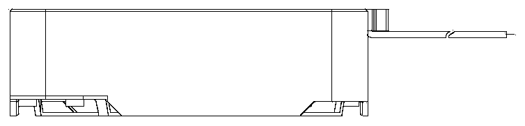
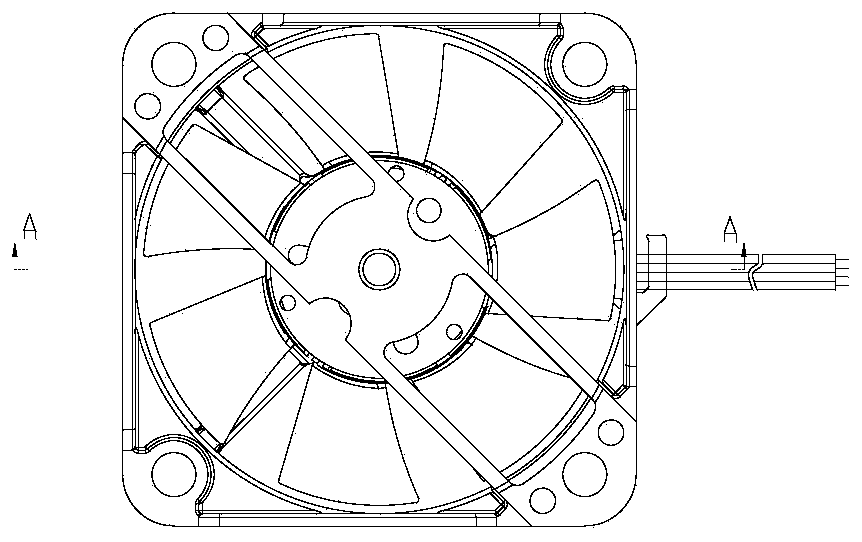
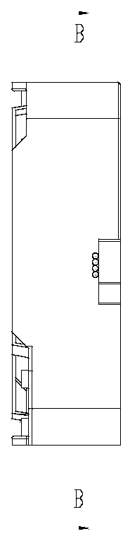
[0045] Such as Figure 1-Figure 11 As shown, a high-temperature-resistant DC brushless cooling fan includes a casing 1, a bearing sleeve 4 is fixed on the lower part of the casing 1, a bearing 7 is wrapped inside the bearing sleeve 4, and a corresponding mated axis 5;

[0046] The bottom of the bearing sleeve 4 passes through the casing 1, and the bottom of the bearing sleeve 4 has at least one c...


PUM


Abstract

The invention discloses a high-temperature-resistant direct-current brushless cooling fan. The high-temperature-resistant direct-current brushless cooling fan comprises a machine shell, a bearing sleeve is fixed at the lower portion inside the machine shell, the bearing sleeve is wrapped around a bearing, a shaft matched with the bearing is arranged in the bearing in a penetrating manner, the bottom of the bearing sleeve penetrates out of the machine shell, moreover, at least one heat dissipation hole is formed in the bottom of the bearing sleeve, a driving circuit board is further arranged atthe upper portion of the bottom of the machine shell, a layer of yoke plate is arranged above the driving circuit board, the shaft, the bearing and the bearing sleeve all penetrate through the driving circuit board and the yoke plate, two hollow coils are arranged on the yoke plate and are symmetrically distributed on the two sides of the shaft, leads of the hollow coils are connected with the driving circuit board, the leads are led out of the driving circuit board to be outside of the machine shell, the upper portion of the shaft is connected with integrally formed fan blades, and magneticsteel is arranged at the positions, opposite to the hollow coils, of the lower surfaces of the fan blades. Due to the hollow coil structure, cooling of the coils is facilitated, and the temperature rise is effectively reduced; the ferrite magnetic steel with quite good temperature resistance is used, and the cost performance is high so that the magnetic force of the magnetic steel can be adjustedquite easily only by increasing the thickness of the magnetic steel.

Description

technical field [0001] The invention relates to the field of high-temperature-resistant cooling fans, in particular to a high-temperature-resistant DC brushless cooling fan. Background technique [0002] The existing DC brushless heat dissipation fan has the problem that the fan itself cannot be directly applied to a high-temperature environment for a long time, specifically the following problems. [0003] 1. Existing heat dissipation fans generally have a traditional iron core structure. Under the influence of heat accumulation effect, the temperature rise of the stator coil is high, and the reliability of the fan is reduced. [0004] 2. The permanent magnet of the existing iron-core fan adopts ring-shaped rubber magnet or other plastic magnets. Due to the limitation of the structure, the thickness cannot be freely increased in the radial direction, and the magnetic force cannot be adjusted freely. In order to improve the remanence of the magnetic steel, more strong magne...

Claims


Application Information

Patent Timeline
Patent Type & Authority Applications(China)
IPC IPC(8): F04D25/08F04D29/056F04D29/063F04D29/58H02K7/14
CPCF04D25/0606F04D25/082F04D29/056F04D29/063F04D29/5806F04D29/5813F04D29/5853H02K7/14
Inventor 张廷友
Owner 风下电机(山东)有限公司
Why Eureka
Try Eureka