Heat exchanger for pure electric automobile cooling system

A pure electric vehicle and cooling system technology, which is applied in the field of heat exchangers used in the cooling system of pure electric vehicles, can solve the problems of waste, heat exchanger copper tubes that cannot be replaced, and the service life of the device is easily affected by copper tubes, etc., so as to achieve easy replacement , the effect of novel structure

Active Publication Date: 2019-11-05
DEZHOU VOCATIONAL & TECHN COLLEGE
View PDF5 Cites 7 Cited by
  • Summary
  • Abstract
  • Description
  • Claims
  • Application Information

AI Technical Summary

Problems solved by technology

[0003] The cartridge type has small volume and high exchange efficiency, but the copper tube in the heat exchanger cannot be replaced, which makes the service life of the whole device easily affected by the copper tube, resulting in waste

Method used


Image

  • Heat exchanger for pure electric automobile cooling system
  • Heat exchanger for pure electric automobile cooling system

Examples


Embodiment 1

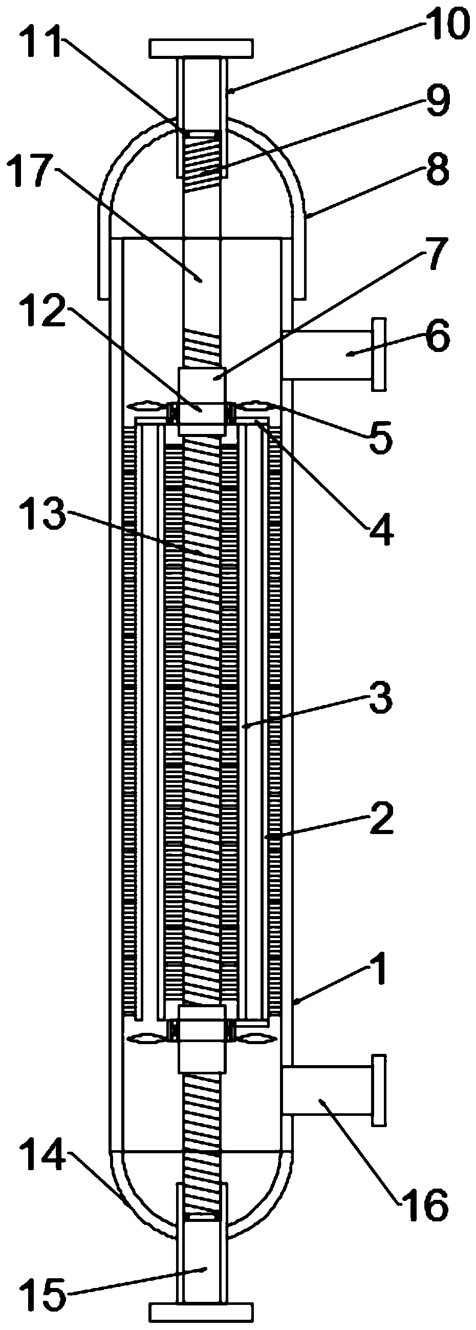
[0017] see figure 1 , in an embodiment of the present invention, a heat exchanger for a pure electric vehicle cooling system includes a cylinder body 1, an upper head 8, a lower head 14 and a copper tube 17, and the top and bottom of the cylinder body 1 are respectively provided with an upper The head 8 and the lower head 14, the upper head 8 is provided with a heat medium inlet pipe 11, the lower head 14 is provided with a heat medium outlet pipe 15, and the upper and lower parts of one side of the cylinder body 1 are respectively provided with a refrigerant outlet pipe 6 And the refrigerant inlet pipe 16, the copper pipe 17 is connected between the heat medium inlet pipe 11 and the heat medium outlet pipe 15 in the cylinder 1, the lower head 14 is welded and fixed to the bottom of the cylinder 1, and the upper head 8 It is threadedly connected with the top of the cylinder 1, and the outer wall of the top of the copper pipe 17 is provided with a first threaded section 9, and ...

Embodiment 2

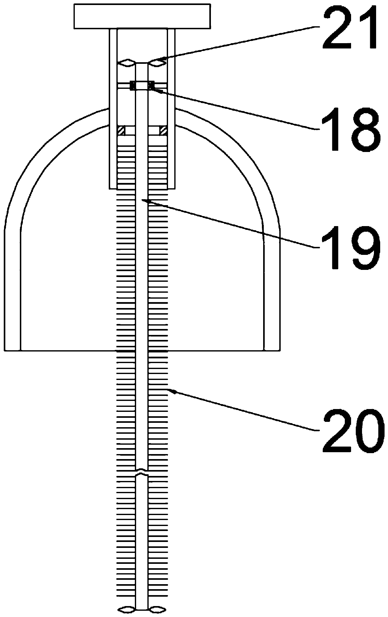
[0019] see figure 2 , The difference between this embodiment and Embodiment 1 is that it also includes a second descaling mechanism, and the second descaling mechanism includes a rotating shaft 19, a second propeller blade 21 and a third brush bar 20, and the rotating shaft 19 Installed in the heat medium inlet pipe 10 through the bearing and the mounting plate 18, the mounting plate 18 is welded and fixed with the heat medium inlet pipe 10 through the support rod, and the third brush bar 20 is installed on the two side walls of the rotating shaft 20, and the two ends of the rotating shaft 19 A plurality of second propeller blades 21 are mounted equidistantly through screw rings. When the heat medium enters the copper pipe 17 from the heat medium inlet pipe 10 and then flows out from the heat medium outlet pipe 15, the second propeller blades 21 drive the rotating shaft 19 to rotate. , the rotating shaft 19 drives the third brush bar 20 to rotate to clean the scale on the inn...


PUM


Abstract

The invention discloses a heat exchanger for a pure electric automobile cooling system. The heat exchanger comprises a barrel body, an upper sealing head, a lower sealing head and a copper pipe; a first descaling mechanism is arranged outside the copper pipe, wherein the first descaling mechanism comprises a sleeve, a second sleeve, propeller blades, a first brush strip and a second brush strip; and the outside of the copper pipe is further comprises a second descaling mechanism, wherein the second descaling mechanism comprises a rotating shaft, second propeller blades and a third brush strip.According to the heat exchanger, the structure is novel, the heat exchanger is convenient to use, the copper pipe is convenient to dismount and replace, the first descaling mechanism and the second descaling mechanism are arranged, the first descaling mechanism comprises the sleeve, the second sleeve, the propeller blades, the first brush strip and the second brush strip, the second descaling mechanism comprises the rotating shaft, the second propeller blades and the third brush strip, the first descaling mechanism and the second descaling mechanism are automatically driven by the power of the refrigerant and the heating medium, and the exchanger can be automatically cleaned, so that the incrustation can prevent from influencing the working efficiency of the heat exchanger.

Description

technical field [0001] The invention relates to the technical field of heat exchangers, in particular to a heat exchanger for a pure electric vehicle cooling system. Background technique [0002] A heat exchanger (also known as a heat exchanger or heat exchange equipment) is a device used to transfer heat from a hot fluid to a cold fluid to meet the specified process requirements. It is an industrial application of convective heat transfer and heat transfer. Heat exchangers can be classified in different ways. According to its operation process, it can be divided into three types: partition type, hybrid type, and regenerative type (or regenerative type); according to the compactness of its surface, it can be divided into two types: compact type and non-compact type. [0003] The cartridge type has small volume and high exchange efficiency, but the copper tubes in the heat exchanger cannot be replaced, so the service life of the whole device is easily affected by the copper ...

Claims


Application Information

Patent Timeline
Patent Type & Authority Applications(China)
IPC IPC(8): F28D7/00F28F9/10F28F9/26F28G3/04
CPCF28D7/00F28F9/10F28F9/26F28F2275/06F28F2275/20F28G3/04
Inventor 杨少波张翠玲
Owner DEZHOU VOCATIONAL & TECHN COLLEGE
Why Eureka
Try Eureka