Method for inhibiting detection luminous power error through atom spinning gyroscope based on magnetic field compensation

A technology of atomic spin and error suppression, which is applied to the size/direction of the magnetic field, the use of magneto-optical equipment for magnetic field measurement, and the direction of steering induction equipment, etc., which can solve the problem that the closed-loop control accuracy of detected optical power is affected by changes in ambient temperature, etc. Achieve the effect of suppressing the gyro angular rate measurement error, reducing the complexity of the system and facilitating miniaturization

Active Publication Date: 2019-11-05
BEIHANG UNIV
View PDF9 Cites 12 Cited by
  • Summary
  • Abstract
  • Description
  • Claims
  • Application Information

AI Technical Summary

Problems solved by technology

[0004] The problem solved by the present invention is: to overcome the shortcomings of the existing SERF atomic spin gyroscope detection optical power closed-loop control accuracy is affected by environmental temperature changes, to provide a detection optical power error suppression method based on magnetic field compensation, not only can make the gyroscope get rid of the Detecting optical closed-loop controls the dependence of optical path and circuit, reduces the complexity of the system, facilitates the miniaturization of gyroscopes, and can be used as a closed-loop solution for atomic spin gyroscopes

Method used


Image

  • Method for inhibiting detection luminous power error through atom spinning gyroscope based on magnetic field compensation
  • Method for inhibiting detection luminous power error through atom spinning gyroscope based on magnetic field compensation
  • Method for inhibiting detection luminous power error through atom spinning gyroscope based on magnetic field compensation

Examples


Embodiment Construction

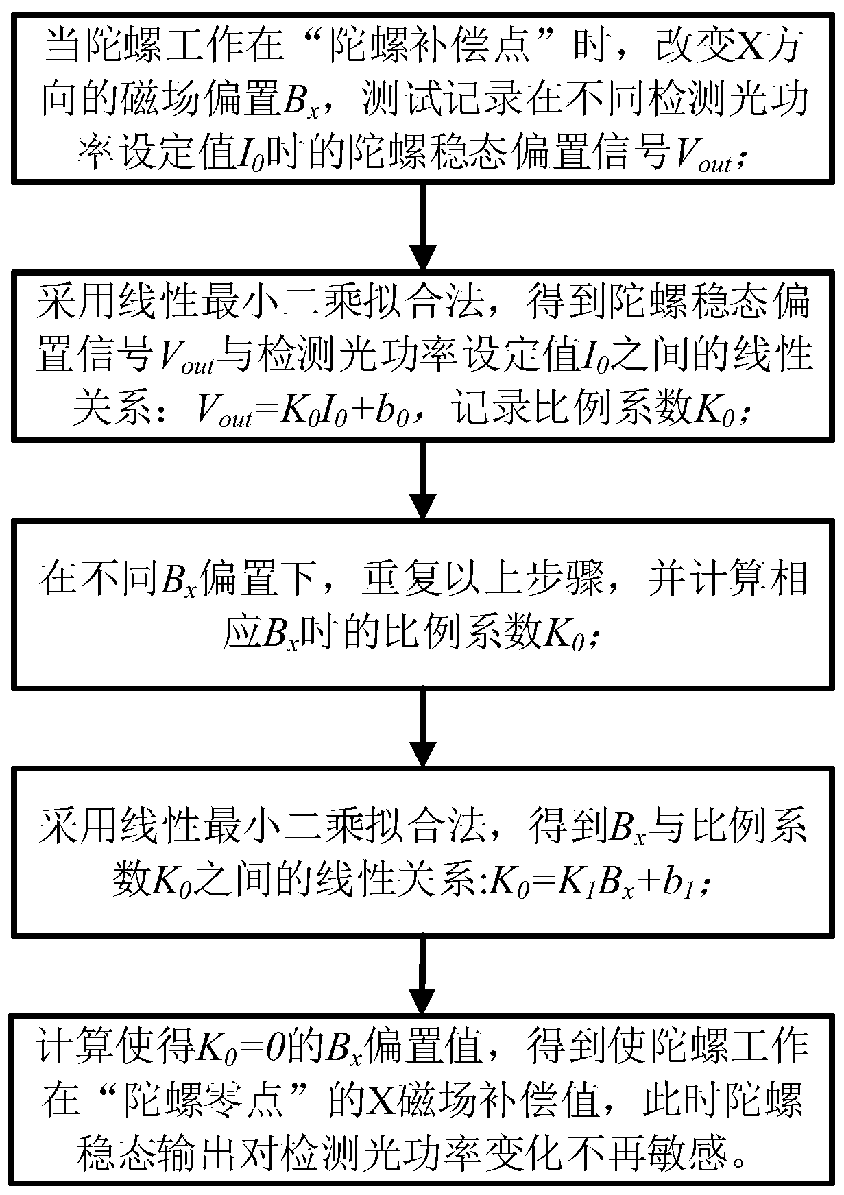
[0028] A magnetic field compensation-based atomic spin gyroscope detection optical power error suppression method. Firstly, the three-dimensional magnetic field compensation in the working state of the gyroscope is reset to zero, and then the sensitivity of the gyroscope to its X-direction magnetic field is used to change the gyroscope applied to the X direction. Magnetic field bias value B x , to obtain the X magnetic field compensation value when the total output bias of the gyroscope is zero, and adjust the working point of the gyroscope from the "gyroscope compensation point" to the "gyroscope zero point". The scale coefficient fluctuation is no longer sensitive, thereby suppressing the measurement error of the gyroscope angular rate caused by the fluctuation of the detected optical power.

[0029] Such as figure 1 As shown, it is a flow chart of the magnetic field compensation-based atomic spin gyroscope detection optical power suppression method of the present invention...


PUM


Abstract

The invention relates to a method for inhibiting a detection luminous power error through an atom spinning gyroscope based on magnetic field compensation. The method comprises the steps that firstly,three-dimensional magnetic field compensation of the working state of the gyroscope is returned to zero, then the gyroscope is used for changing a magnetic field offset value Bx applied in the X direction according to the sensitivity characteristic of the magnetic field in the X direction of the gyroscope, an X direction magnetic field compensation value when the total output offset value of the gyroscope is zero is obtained, a working point of the gyroscope is adjusted to a gyroscope null point from a gyroscope compensation point, at this moment, a gyroscope output signal is not sensitive tocalibration factor fluctuation caused by change of the detection luminous power, so that the gyroscope angular seed measurement error caused by detection luminous power fluctuation is completely inhibited, and the stability of the gyroscope is improved. According to the method, the gyroscope can get rid of dependency on a detection light closed-loop control optical path and a circuit, the system complexity is lowered, and the method is beneficial to gyroscope miniaturization and can be used as a loop closing scheme for the atom spinning gyroscope.

Description

technical field [0001] The invention relates to an atomic spin gyroscope detection optical power error suppression method based on magnetic field compensation, which belongs to the field of atomic gyroscopes and can also be used in the field of atomic magnetometers. Background technique [0002] The atomic spin gyroscope based on spin-exchange relaxation-free (Spin-Exchange Relaxation-Free, SERF) technology has the characteristics of high theoretical precision, small size, low cost, and small dynamic range, and is suitable for future platform inertial navigation systems. Bias stability is an important evaluation index of gyroscope, which directly determines the accuracy of inertial navigation system. The SERF atomic spin gyroscope realizes the polarization of atoms through a beam of circularly polarized pumping light, and realizes the detection of atomic spin precession signals through a beam of linearly polarized detection light. When the gyro works at the "gyro compensati...

Claims


Application Information

Patent Timeline
Patent Type & Authority Applications(China)
IPC IPC(8): G01C19/60G01R33/032
CPCG01C19/60G01R33/032
Inventor 全伟范文峰刘峰张伟佳黄炯阮家森刘刚
Owner BEIHANG UNIV
Why Eureka
Try Eureka