Full-electronic terahertz tomography device and control method thereof

A tomographic imaging and terahertz technology, applied in the field of terahertz imaging, can solve the problems of low test efficiency and achieve the effect of improving test efficiency and high imaging resolution

Active Publication Date: 2019-11-05
CHINA ELECTRONIS TECH INSTR CO LTD
View PDF6 Cites 4 Cited by
  • Summary
  • Abstract
  • Description
  • Claims
  • Application Information

AI Technical Summary

Problems solved by technology

[0003] For terahertz imaging, the inventor found in the research and development process that the current common method is to install the terahertz transceiver module or the sample under test on a mechanical motion device for scanning. This met

Method used


Image

  • Full-electronic terahertz tomography device and control method thereof

Examples


Example Embodiment

[0028] Example one

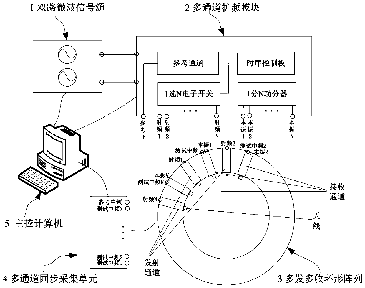
[0029] This embodiment provides an all-electronic terahertz tomography device. The device adopts a multi-transmit and multi-receive terahertz signal generation and reception form, which can realize the rapid acquisition of the scattering information of the measured sample; in addition, because the transmission and reception interval is arranged Annular array, the obtained scattering data of the sample under test contains both reflection and transmission information, and then high-resolution imaging of the sample under test is realized through the contrast source algorithm, and the imaging resolution is better than half a wavelength.

[0030] See attached figure 1 The device includes a dual-channel microwave signal source 1, a multi-channel spread spectrum module 2, a multi-transmit and multi-receive terahertz ring array 3, a multi-channel synchronous acquisition unit 4 and a main control computer 5.

[0031] The two-channel microwave signal source 1 is used to g...

Example Embodiment

[0054] Example two

[0055] This embodiment provides a control method of an all-electronic terahertz tomography device, which is implemented based on the all-electronic terahertz tomography device described in the first embodiment. The method includes the following steps:

[0056] S101: The main control computer 5 sends a frequency setting instruction to the dual-channel microwave signal source, and sets the radio frequency and local oscillator signals of the dual-channel microwave signal source according to the frequency setting instruction.

[0057] S102: After the frequency is set successfully, the main control computer 5 sends an electronic switch switching instruction to the multi-channel spread spectrum module, so that the 1 select N electronic switch is switched to the nth transmitting channel (n=0,1,...,N).

[0058] S103: After the electronic switch is switched, the main control computer 5 sends a trigger signal to the dual-channel microwave signal source and the multi-channel...


PUM


Abstract

The invention discloses a full-electronic terahertz tomography device and a control method thereof. The full-electronic terahertz tomography device comprises a dual-path microwave signal source for generating a path of radio frequency microwave signals and a path of local oscillator microwave signals, a multi-channel spread spectrum module for seperately expanding one path of radio frequency microwave signals and one path of local oscillator microwave signals into N paths of radio frequency microwave signals and N paths of local oscillator microwave signals and generating one path of referenceintermediate-frequency signals, a multi-transmitting multi-receiving terahertz annular array for respectively carrying out frequency multiplication and amplification on N paths of radio frequency microwave signals and N paths of local oscillator microwave signals to generate N paths of terahertz transmitting signals and N paths of terahertz local oscillator signals, and mixing the N paths of terahertz local oscillator signals with scattering signals of N paths of tested samples to obtain N paths of testing intermediate-frequency signals, a multi-channel synchronous acquisition unit for acquiring N paths of testing intermediate-frequency signals and a path of reference intermediate-frequency signals, and a master control computer acquiring and processing the scattering data of a tested sample and realizing high-resolution imaging of the tested sample through a contrast source algorithm.

Description

technical field [0001] The present disclosure relates to the technical field of terahertz imaging, in particular to an all-electronic terahertz tomography device and a control method thereof. Background technique [0002] Terahertz waves are located between microwaves and infrared rays, and have physical properties such as no ionizing radiation, high resolution, harmlessness to the human body, and strong penetrability. Terahertz imaging can obtain images of the spatial density distribution of substances, so terahertz imaging is especially suitable for applications such as internal structure measurement and defect imaging of materials that are invisible to visible light and have insufficient X-ray contrast. Compared with ultrasonic waves, terahertz waves have small attenuation, deep penetration, and short wavelength in the tested sample, and can obtain high-resolution imaging effects, which can visually display internal defects; compared with X-rays, it will not be destroyed ...

Claims


Application Information

Patent Timeline
IPC IPC(8): G01N21/3581G01N21/01
CPCG01N21/01G01N21/3581G01N2021/0112
Inventor 孙超常庆功王亚海米郁年夫顺
Owner CHINA ELECTRONIS TECH INSTR CO LTD
Why Eureka
Try Eureka