electrical connector

A technology of electrical connectors and contact parts, which is applied in the direction of connection, fixed connection, and parts of connection devices, etc., which can solve the problems of broken elastic arms, affecting the electrical connection between terminals and the chip module, and detachment of fish eyes , to achieve a stable and in-place electrical connection

Active Publication Date: 2021-05-25
DEYI PRECISION ELECTRONIC IND CO LTD PANYU
View PDF0 Cites 0 Cited by
  • Summary
  • Abstract
  • Description
  • Claims
  • Application Information

AI Technical Summary

Problems solved by technology

[0003] However, during the process of installing the terminal into the through hole, since the connection relationship between the terminal and the through hole of the body is not fixedly connected, and the electrical connector is not provided with a stop The stop part that prevents the terminal from moving toward the chip module side makes the terminal easy to move toward the chip module side so that the fisheye part is detached from the through hole, resulting in the fisheye part The two sides cannot abut and connect with the conducting part, thereby causing the electrical connection between the terminal and the body to be unable to be realized
And when the chip module presses the elastic arm downwards, since the electrical connector does not provide a support portion between the elastic arm and the base to prevent the chip module from excessively pressing down on the elastic arm , so when the chip module excessively presses down on the elastic arm, it is easy to cause irreversible deformation of the elastic arm, and even cause the breakage of the elastic arm, thereby affecting the electrical connection between the terminal and the chip module. sex guide

Method used


Image

  • electrical connector
  • electrical connector
  • electrical connector

Examples


Embodiment Construction

[0052] In order to facilitate a better understanding of the purpose, structure, features, and effects of the present invention, the present invention will now be further described in conjunction with the accompanying drawings and specific embodiments.

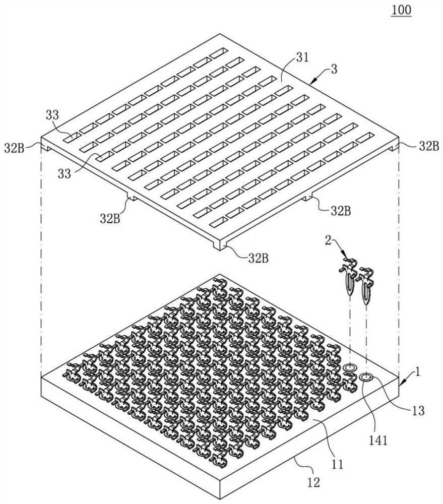
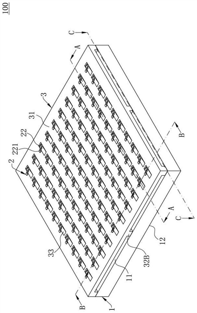
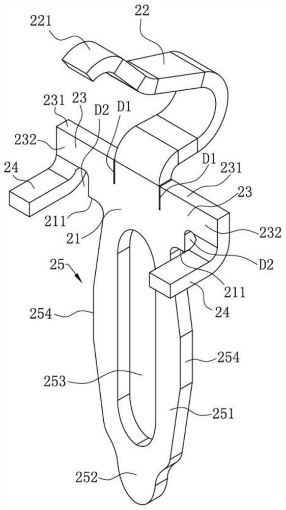
[0053] Such as figure 1 , figure 2 with Figure 9 As shown, the electrical connector 100 of the first embodiment of the electrical connector of the present invention is used to electrically connect a chip module 200 to a circuit board 300. The electrical connector 100 includes a body 1 and is accommodated in the body 1 A plurality of terminals 2 and a cover 3 arranged above the body 1 . The terminal 2 is electrically connected to the body 1, and one end of the terminal 2 elastically contacts the chip module 200 to realize the electrical connection between the terminal 2 and the chip module 200, so The other end of the terminal 2 is soldered to the circuit board 300 through a solder 4 to realize the electrical connection bet...


PUM


Abstract

The invention discloses an electrical connector, which comprises: a body including an upper surface and a connecting portion; a cover body arranged on the top of the body, the cover body is provided with a through groove, and the cover body is provided with a supporting surface and a limiting surface arranged toward the body , the supporting surface abuts against the body downwards, and the limit surface is set higher than the upper surface; the terminal is connected to the connecting part, and the terminal includes a base, an elastic arm extending upward from the base and an extension extending from the base, and the elastic arm penetrates upward Through the slot, the elastic arm has a contact portion for connecting with the chip module, and the extension portion is provided with a stop surface facing the limit surface, the stop surface is located between the upper surface and the limit surface, and the limit surface stops Move face up. The cover body supports the chip module upwards, preventing the elastic arm from being irreversibly deformed or broken due to excessive pressing, and ensuring the connection between the terminal and the chip module. The limit surface stops the upward movement of the stop surface, prevents the terminal from moving upwards excessively relative to the body toward the chip module, and ensures that the connection between the terminal and the connecting part is stable and in place.

Description

【Technical field】 [0001] The invention relates to an electrical connector, in particular to an electrical connector with functions of limiting and supporting. 【Background technique】 [0002] An existing electrical connector includes a body and a plurality of terminals accommodated in the body. The body is provided with a plurality of through holes, and a plurality of the terminals are respectively accommodated in the plurality of through holes in one-to-one correspondence, and the inner wall of the through hole is provided with a conducting portion. The terminal is provided with a base, and the base is carried on the body. A fish-eye part is extended from the base part toward the through hole, and the two sides of the fish-eye part abut and connect with the connecting part respectively, so as to realize the electrical connection between the terminal and the body. sex lead. An elastic arm extends upward from the base, and the elastic arm is used for electrical connection w...

Claims


Application Information

Patent Timeline
Patent Type & Authority Patents(China)
IPC IPC(8): H01R12/71H01R13/502H01R13/436H01R13/24H01R12/57
CPCH01R12/57H01R12/714H01R12/716H01R13/24H01R13/2414H01R13/4365H01R13/502
Inventor 张军
Owner DEYI PRECISION ELECTRONIC IND CO LTD PANYU
Why Eureka
Try Eureka