Combined high-current stamping terminal and reed structure

A high-current, combined technology, applied in the direction of circuits, electrical components, coupling devices, etc., can solve the problems of complicated installation, unreasonable conduction structure design, and narrow installation space of wiring in the car, so as to achieve high contact stability of connection current, The connection method is flexible and changeable, and it is easy to adjust the effect of tolerance consistency

Inactive Publication Date: 2019-11-05
胡世勇
View PDF9 Cites 15 Cited by
  • Summary
  • Abstract
  • Description
  • Claims
  • Application Information

AI Technical Summary

Problems solved by technology

[0003] At present, the market is mainly metal shell multi-core connectors. Such connector products usually have the following disadvantages: 1. Unreasonable conduction structure design, complicated installation, poor contact, and unstable resistance lead to increased heat generation; 2. The product process is complicated and the cost is high. ; 3. Due to the narrow installation space of the wiring in the car, there will be some inconvenience when installing the traditional one-way contact connector; 4. The flexible and variable single-plug connection

Method used


Image

  • Combined high-current stamping terminal and reed structure
  • Combined high-current stamping terminal and reed structure
  • Combined high-current stamping terminal and reed structure

Examples


Embodiment 1

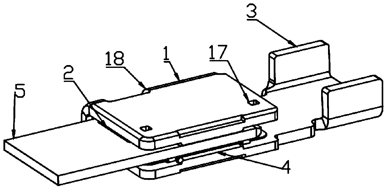
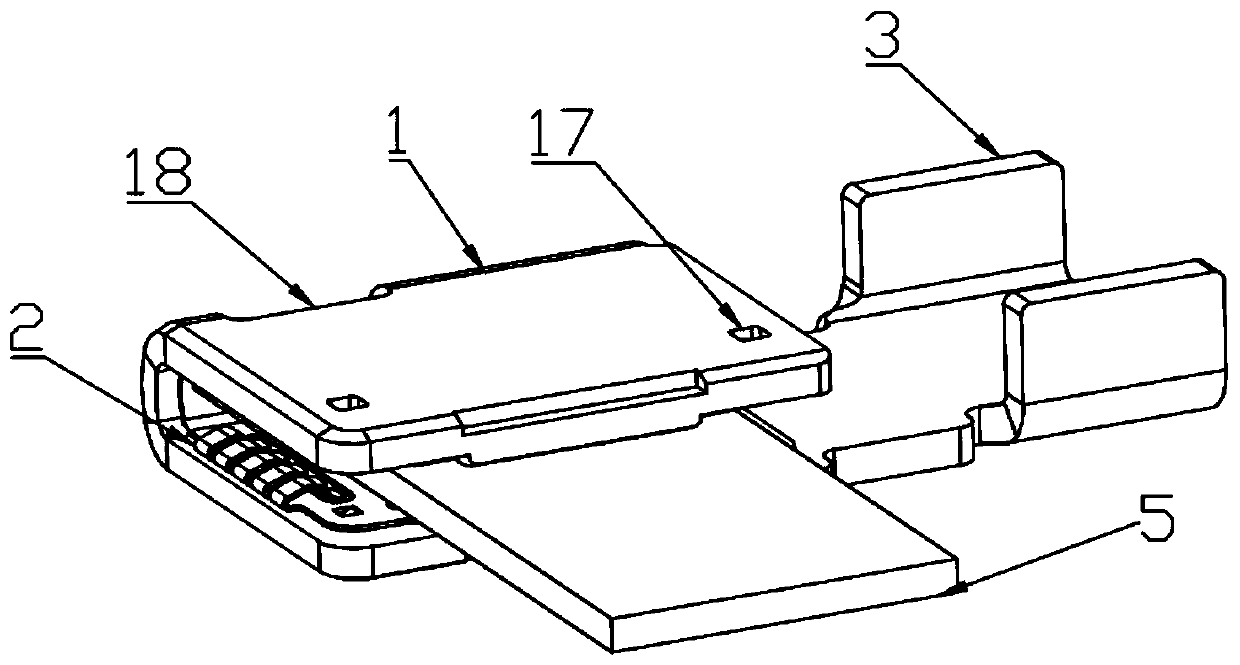
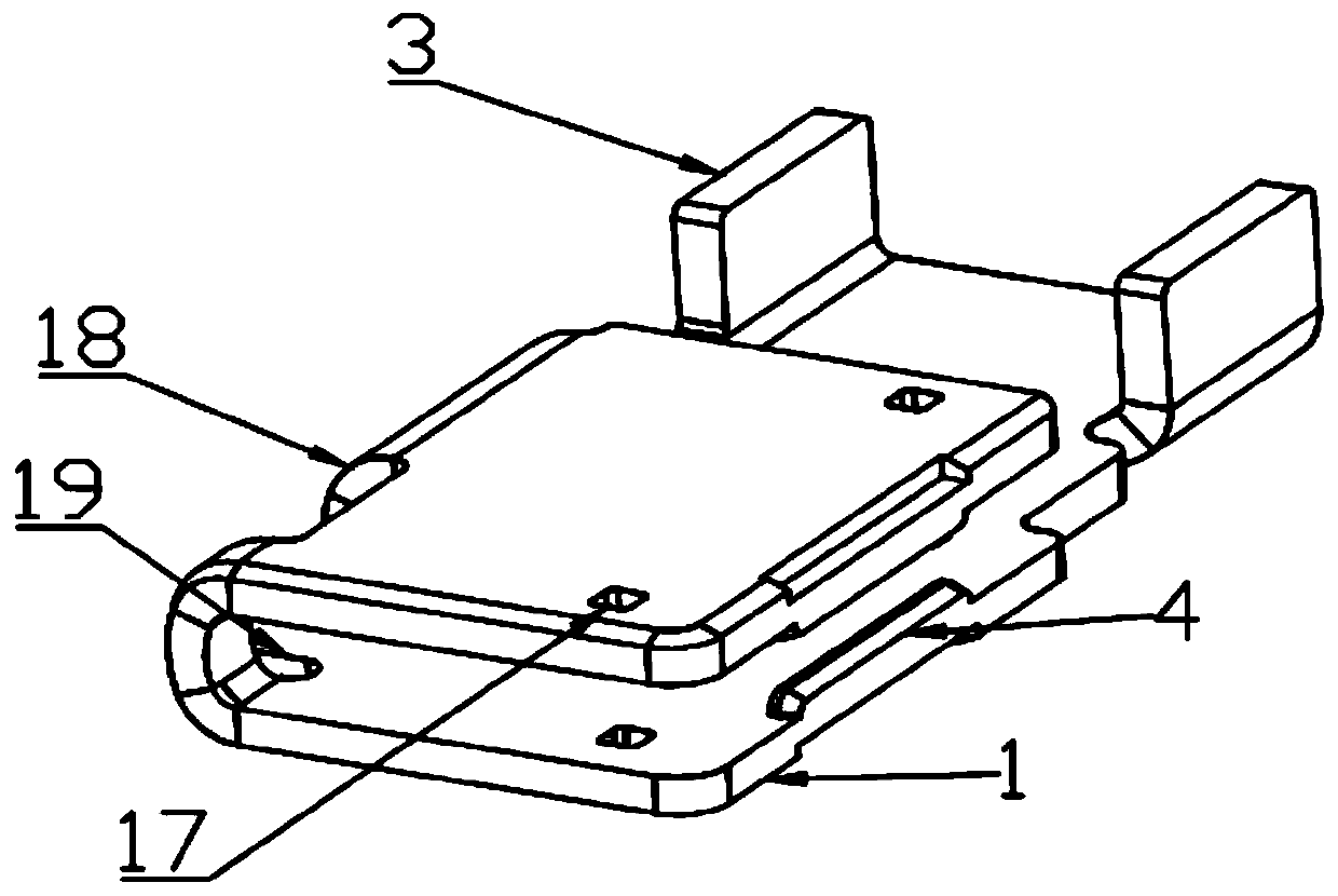
[0023] Such as Figure 1 to Figure 7 As shown, a combined high-current stamping terminal and reed structure includes a "U"-shaped opening-shaped sheath body 1 and a reed body 2. The side end of the sheath body 1 is connected with a copper wire for fixing the cable. The sheath wire lug 3 of the core, the upper and lower ends of the opening of the sheath body 1 are provided with a pair of plug-in limit ribs 4 with guide angles, and the reed body 2 is embedded in the sheath body 1 and is used for inserting copper bars sheet 5, the reed main body 2 includes a plurality of guiding contact fingers 1 6, guiding contact fingers 2 7 and contact contact fingers 8, and the reed main body 2 has a strip-shaped opening 9 and a strip-shaped opening 9 and a strip opening respectively at adjacent two sides. Shaped opening two 10, several guide contact fingers one 6 and guide contact fingers two 7 are bow tongue-shaped and the roots are connected with the reed main body 2 at a certain bow angle...

Embodiment 2

[0032] Such as Figure 8 As shown, the difference from Embodiment 1 is that the reed main body 2 is still embedded in the sheath main body 1, and the original clamping connection mode is changed to a plurality of fixing columns 20 fixed on the sheath main body 1. The connection mode of riveting with the reed main body 2.

[0033] Based on the above, the present invention has the following beneficial effects: 1. Ensure high electrical conductivity while satisfying simplicity, convenient installation and operation, and high contact stability of the connection current; 2. The product structure is changed from the traditional machining process to the sheet metal stamping process. , easy to adjust tolerance consistency. Avoid inconsistencies in product performance due to accumulated tolerances; 3. The product structure is converted from traditional cylinders to sheet metal stamping, which is improved to increase contact points at equal volumes while satisfying 90° and 180° two-way...


PUM


Abstract

The invention discloses a combined high-current stamping terminal and reed structure, and relates to the technical field of electrical connectors. The combined high-current stamping terminal and reedstructure comprises a sheath main body with a U-shaped opening and a reed main body, wherein the side end of the sheath main body is connected with sheath lugs used for fixing a cable copper core, theupper and lower ends of the opening of the sheath main body are respectively provided with opposite insertion limiting bones with guide angles, the reed main body is embedded in the sheath main bodyand used for inserting a copper bar insertion piece, and the reed main body includes a plurality of guide contact fingers I, guide contact fingers II and contact fingers. The combined high-current stamping terminal and reed structure meets the requirements of simple and convenient installation and operation and high contact stability of connecting current while ensuring high conductivity; the tolerance consistency is easy to adjust, and the performance inconsistency of products caused by the accumulated tolerance is avoided; two-way contact of 90 degrees and 180 degrees is met while increasingcontacts points in equal volume; and the connection can be realized by crimping, welding and bolt fastening, and the flexibility and variability of the connection mode of the cable are realized.

Description

technical field [0001] The invention relates to the technical field of electrical connectors, in particular to a combined high-current stamping terminal and reed structure. Background technique [0002] With the country's vigorous promotion of energy conservation and environmental protection, more and more new energy vehicles are used. High-voltage and high-current connectors are an indispensable connector in new energy vehicles. The market demand for high-voltage and high-current connectors is also increasing. As the size increases, the requirements for safety performance and product optimization are also getting higher and higher. [0003] At present, the market is mainly metal shell multi-core connectors. Such connector products usually have the following disadvantages: 1. Unreasonable conduction structure design, complicated installation, poor contact, and unstable resistance lead to increased heat generation; 2. The product process is complicated and the cost is high. ...

Claims


Application Information

Patent Timeline
Patent Type & Authority Applications(China)
IPC IPC(8): H01R13/02H01R13/03H01R13/24H01R13/42H01R13/629
CPCH01R13/02H01R13/03H01R13/24H01R13/42H01R13/629
Inventor 胡世勇
Owner 胡世勇
Why Eureka
Try Eureka