
Signal transmission method applied to relay technology and related equipment

A technology for signal transmission and communication equipment, which is applied in the field of signal transmission methods and related equipment, and can solve the problems of interfering with the signal sent by a relay node B, cross-link interference, etc.

Active Publication Date: 2019-11-05
CHENGDU HUAWEI TECH
View PDF4 Cites 5 Cited by
  • Summary
  • Abstract
  • Description
  • Claims
  • Application Information

AI Technical Summary

Problems solved by technology

[0003] However, in the IAB scenario, when relay node A transmits signals in TDM mode and relay node B receives signals in SDM mode, and the distance between relay node A and relay node B is relatively close, the transmission of relay node A The signal will interfere with the transmitted signal of the relay node B, resulting in cross-link interference

Method used


Image

  • Signal transmission method applied to relay technology and related equipment
  • Signal transmission method applied to relay technology and related equipment
  • Signal transmission method applied to relay technology and related equipment

Examples


Embodiment Construction

[0065] Embodiments of the present application provide a signal processing method and related equipment applied to relay technology, so as to implement low-overhead cross-link interference management.

[0066] The terms "first", "second", "third", "fourth", etc. (if any) in the specification and claims of the present application and the above drawings are used to distinguish similar objects, and not necessarily Used to describe a specific sequence or sequence. It is to be understood that the terms so used are interchangeable under appropriate circumstances such that the embodiments described herein can be practiced in sequences other than those illustrated or described herein. Furthermore, the terms "comprising" and "having", as well as any variations thereof, are intended to cover a non-exclusive inclusion, for example, a process, method, system, product or device comprising a sequence of steps or elements is not necessarily limited to the expressly listed instead, may includ...


PUM


Abstract

The embodiment of the invention discloses a signal transmission method applied to a relay technology and related equipment, which are used for realizing low-overhead cross-link interference management. The method provided by the embodiment of the invention comprises the following steps: a second node receives a first signal sent by a first node, wherein the first signal comprises information of time resources occupied by the first node during backhaul transmission and a transceiving state of the first node during backhaul transmission; and when the transceiving state of the first node during backhaul transmission is different from the transceiving state of the second node during backhaul transmission, the second node transmits and receives signals on resources except time resources occupied by the first node during backhaul transmission.

Description

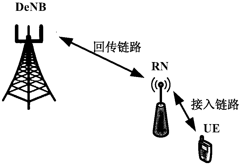
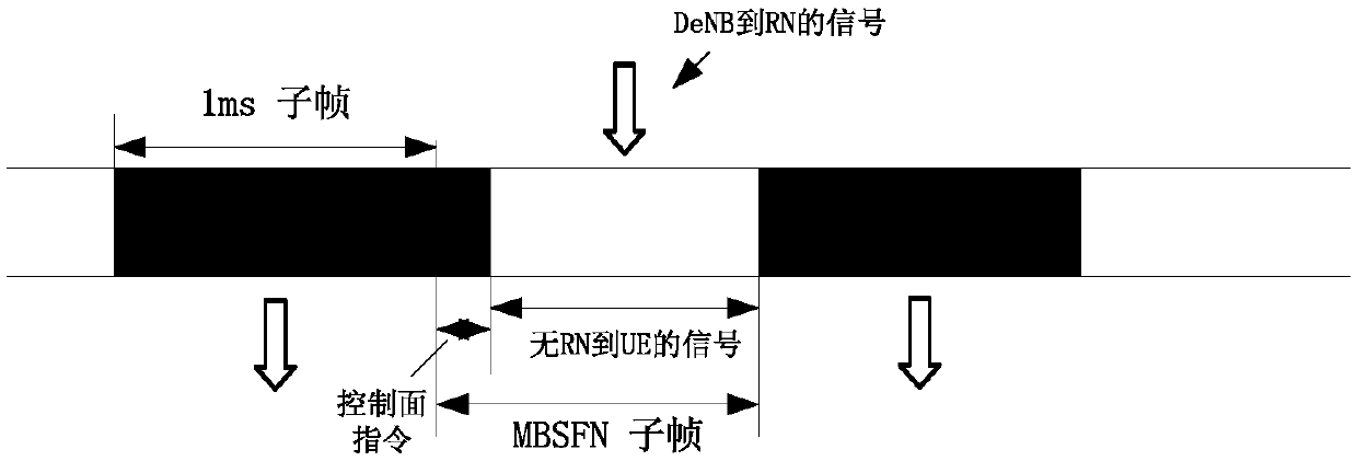
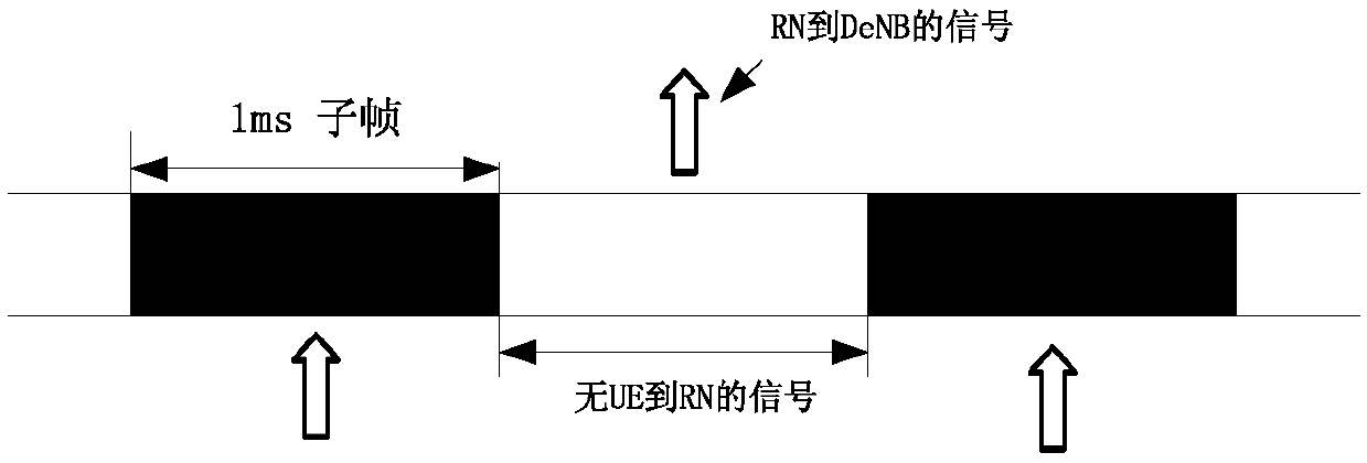
technical field [0001] The present application relates to the field of wireless communication, and in particular to a signal transmission method applied to relay technology and related equipment. Background technique [0002] The long term evolution (long term evolution, LTE) LTE system introduces the relay technology (relaying). The relay technology deploys a relay node (relay node, RN) in the network to forward the base station (evolved node B, eNB) and The data between terminals (user equipment, UE) achieves the purpose of enhancing network capacity, solving backhaul connections between base stations, and solving coverage blind spots. figure 1 It is a possible network structure diagram, including a donor base station (donor eNB, DeNB), RN and UE. The RN is connected to the DeNB through a wireless interface, and the UE is connected to the RN or eNB through a wireless interface. The link between DeNB and RN is called backhaul link, and the link between RN and UE is called...

Claims


Application Information

Patent Timeline
Patent Type & Authority Applications(China)
IPC IPC(8): H04W72/04
CPCH04W72/0446H04W72/20H04W72/23H04W24/02H04W84/047H04W72/541H04J11/005H04W72/29
Inventor 唐小勇邱晶
Owner CHENGDU HUAWEI TECH
Learn More