Surgical instrument disinfection equipment

A technology for disinfection equipment and surgical instruments, applied in the field of surgery, can solve the problems of inconvenient search, bacterial contamination, inconvenient access of surgical instruments, etc., and achieve the effect of easy access and easy search

Inactive Publication Date: 2019-11-08
马雪
View PDF8 Cites 0 Cited by
  • Summary
  • Abstract
  • Description
  • Claims
  • Application Information

AI Technical Summary

Problems solved by technology

[0002] During the operation, sometimes it is inconvenient to take and find the surgical instruments, or in the disinfection process of the postoperative instruments, there may be new pollution sources after disinfection, resulting in bacterial contamination after disinfection. The present invention solves the above problems

Method used


Image

  • Surgical instrument disinfection equipment
  • Surgical instrument disinfection equipment
  • Surgical instrument disinfection equipment

Examples


specific Embodiment approach 1

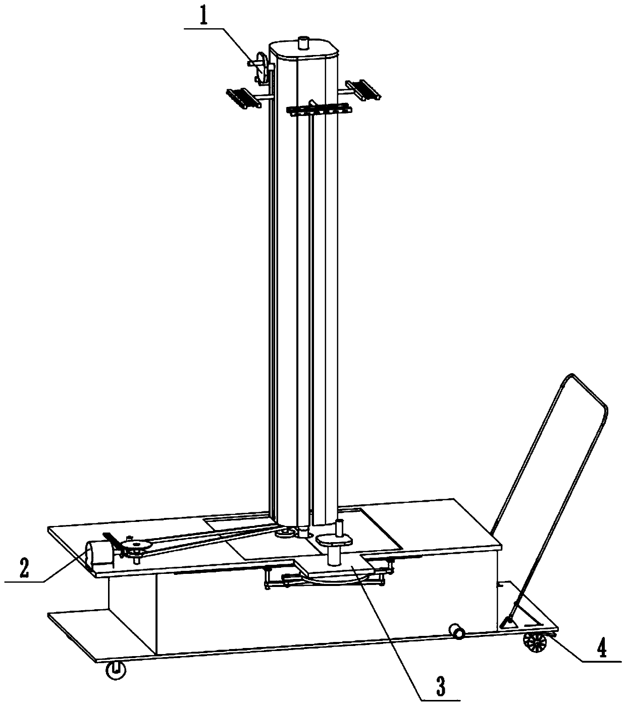
[0027] Combine below Figure 1-12 Describe this embodiment, a surgical instrument disinfection equipment, including an instrument fixing assembly 1, a power assembly 2, a door opening assembly 3 and a walking assembly 4, the instrument fixing assembly 1 is engaged with the power assembly 2, and the door is opened The assembly 3 is connected with the power assembly 2 , the instrument fixing assembly 1 is connected with the walking assembly 4 , and the walking assembly 4 is connected with the power assembly 2 .

specific Embodiment approach 2

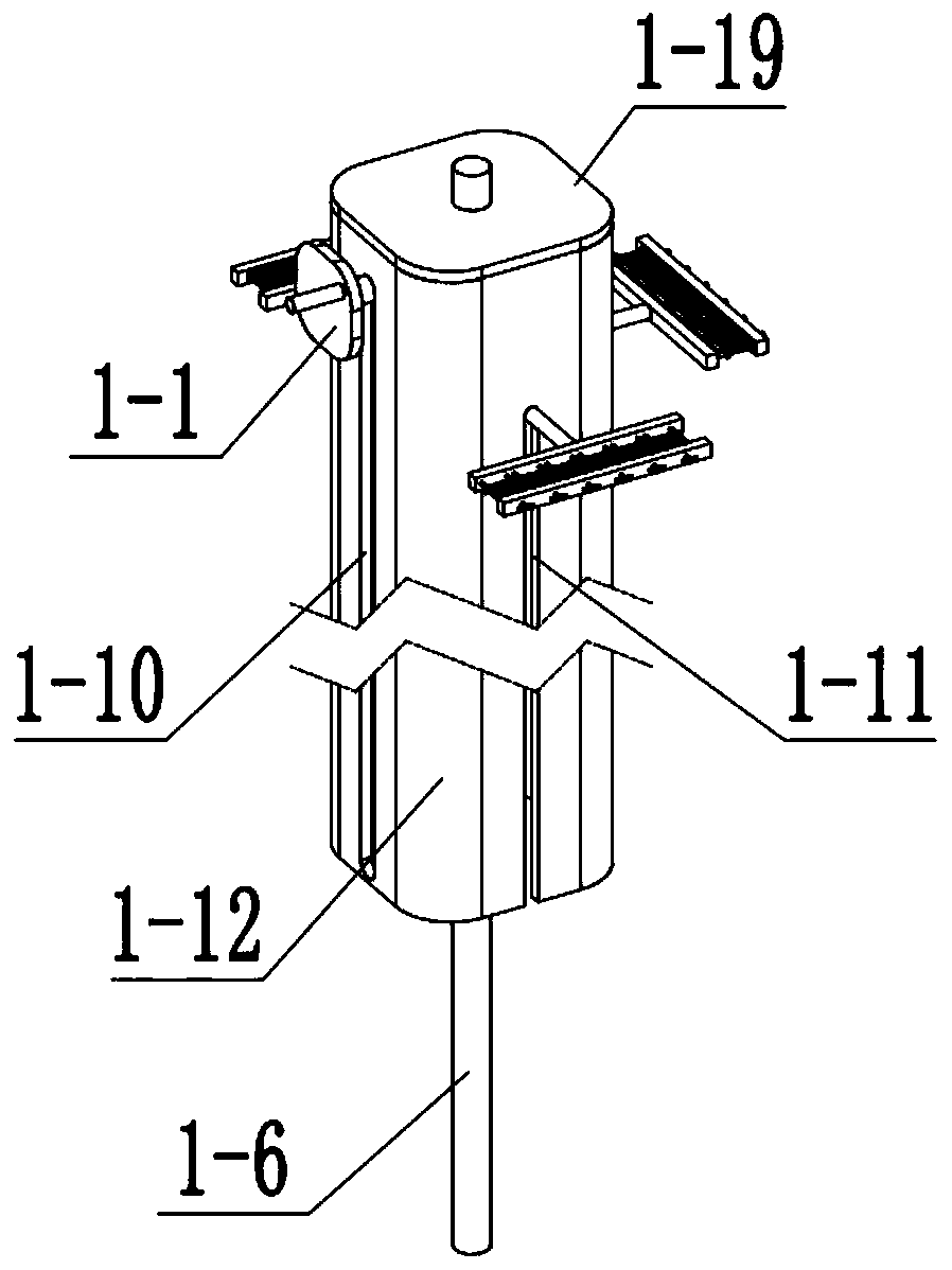
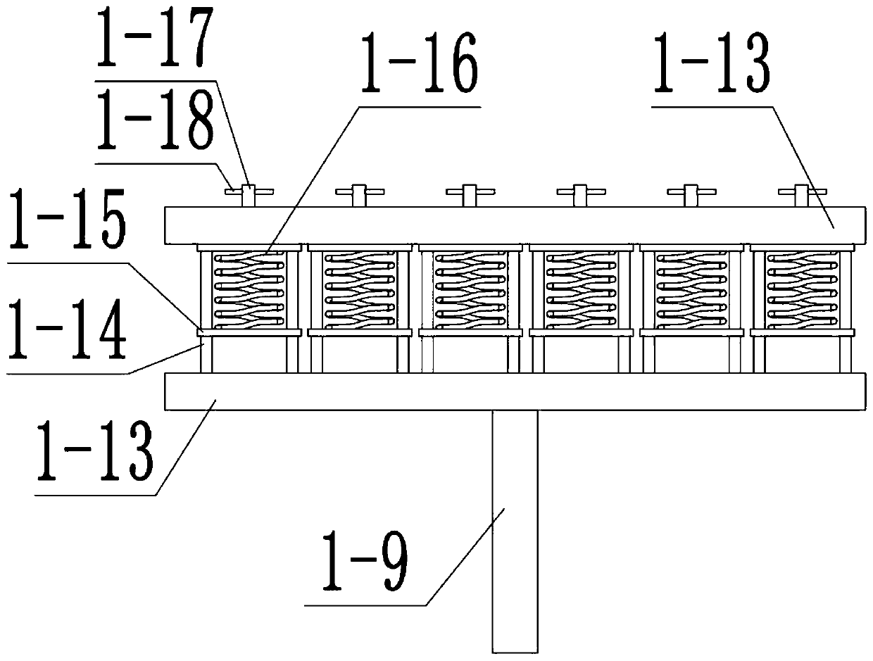
[0029] Combine below Figure 1-12 Describe this embodiment, this embodiment will further explain the first embodiment, the instrument fixing assembly 1 includes the handle I1-1, the handle I shaft 1-2, the lifting bevel gear I1-3, the lifting bevel gear II1- 4. Threaded sleeve 1-5, lifting shaft 1-6, rotating sleeve 1-7, gear cylinder 1-8, rotating rod 1-9, rotating shaft slide rail 1-10, rotating rod sliding rail 1-11 , lifting shell 1-12, clip bracket 1-13, clip sliding column 1-14, clip 1-15, square spring 1-16, threaded rotary column 1-17, rotary rod 1-18, lifting shell end cover 1- 19. Rotary shaft bracket 1-20, rotary shaft bracket slide plate 1-21, threaded sleeve connecting frame 1-22, threaded sleeve groove 1-23 and slide rail 1-24, rotary handle I 1-1 and rotary The shaft 1-2 of the handle I is connected, the shaft 1-2 of the rotary handle I is connected with the lifting bevel gear I1-3, the lifting bevel gear I1-3 is meshed with the lifting bevel gear II1-4, and th...

specific Embodiment approach 3

[0031] Combine below Figure 1-12 Describe this embodiment, this embodiment will further explain the first embodiment, the power assembly 2 includes a motor 2-1, a motor shaft 2-2, a bevel gear I 2-3, a bevel gear II 2-4, a bevel gear II shaft 2-5, pulley Ⅰ2-6, V belt 2-7, pulley Ⅱ2-8, pulley Ⅱ shaft 2-9, slider 2-10, extension spring 2-11, chute Ⅰ2-12, pulley Ⅲ2-13, belt wheel Ⅲ shaft 2-14, gear 2-15, chute Ⅱ2-16, disinfection inlet 2-17 and disinfection upper plate 2-18, motor 2-1 is connected with motor shaft 2-2, and the motor Shaft 2-2 is connected with bevel gear Ⅰ 2-3, bevel gear Ⅰ 2-3 is meshed with bevel gear Ⅱ 2-4, bevel gear Ⅱ 2-4 is connected with bevel gear Ⅱ shaft 2-5, bevel gear Ⅱ shaft 2-5 Connected with pulley Ⅰ2-6, bevel gear Ⅱ shaft 2-5 is rotationally connected with disinfection upper plate 1-18, pulley Ⅰ2-6, pulley Ⅱ2-8, pulley Ⅲ2-13 and V-belt 2-7 belt turn. Pulley II 2-8 is rotationally connected with pulley II shaft 2-9, pulley II shaft 2-9 is connec...


PUM


Abstract

The invention relates to the field of surgery, in particular to surgical instrument disinfection equipment. The surgical instrument disinfection equipment comprises an instrument fixing combination body, a power combination body, a door opening combination body and a walking combination body. In an operation, the problems that an operation instrument is not convenient to take and inconvenient to find, or the disinfection treatment of postoperative instruments can be prevented from colliding with a new pollution source after being disinfected, the sterilized bacteria are polluted is solved. Thesurgical instrument disinfection equipment solves the above problem. The surgical instrument can be inserted into a clamp and is convenient to take, a surgical instrument rack can be lifted and can be adjusted to the height which can be conveniently taken by a user, a square spring is adjusted, the surgical instrument can be clamped by the clamp, the surgical instrument rack is descended to the lowest point, a power device drives the surgical instrument rack to rotate in the disinfectant, dirt on the surface of the instrument is scoured, and meanwhile, the disinfectant is fully contacted anddisinfected with the surface of the instrument.

Description

technical field [0001] The invention relates to the field of surgery, more specifically to a surgical instrument disinfection equipment. Background technique [0002] During the operation, sometimes it is inconvenient to take and find surgical instruments, or in the disinfection process of postoperative instruments, new pollution sources may be encountered after disinfection, resulting in bacterial contamination after disinfection. The present invention solves the above problems. Contents of the invention [0003] The purpose of the present invention is achieved through the following technical solutions: [0004] A surgical instrument disinfection equipment, including an instrument fixing assembly, a power assembly, a door opening assembly and a walking assembly, the instrument fixing assembly is meshed with the power assembly, the door opening assembly is connected to the power assembly, and the instrument is fixed The assembly is connected with the walking assembly, and...

Claims


Application Information

Patent Timeline
IPC IPC(8): B08B3/10B08B3/08A61L2/18
CPCA61L2/18B08B3/08B08B3/10
Inventor 马雪
Owner 马雪
Why Eureka
Try Eureka