Assembly type building outer wall steel structure welding clamping device
A technology for building exterior walls and steel structures, applied to auxiliary devices, welding equipment, auxiliary welding equipment, etc., can solve problems that affect work efficiency, large volume, troublesome adjustment and fixed installation methods, etc., and achieve the effect of ensuring accuracy
- Summary
- Abstract
- Description
- Claims
- Application Information
AI Technical Summary
Problems solved by technology
Method used
Image
Examples
Embodiment 1
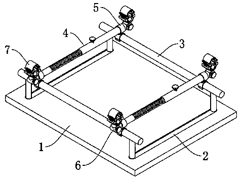
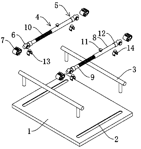
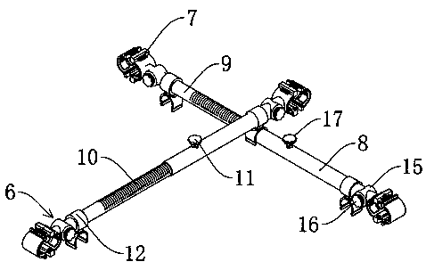
[0030] see Figure 1-3, an assembly type building exterior wall steel structure welding clamping device, including a mounting base 1 and a connecting frame 3, the two sides of the upper surface of the mounting base 1 are provided with chute 2, and the connecting frame 3 is slidably installed inside the chute 2, The connecting frame 3 is provided with a telescopic mechanism 4, and the telescopic mechanism 4 includes a connecting rod 8 and a telescopic rod 9. The telescopic rod 9 is telescopically connected with the connecting rod 8. The first locking bolt 11 is spirally connected on the outer wall, and the connecting rod 8 and the telescopic rod 9 are also connected with a clamping mechanism 5, and the telescopic mechanism 4 is clamped on the connecting frame 3 through the clamping mechanism 5. An angle adjustment mechanism 6 is also connected, and a fixed clamping mechanism 7 is connected to the angle adjustment mechanism 6 .
[0031] The clamping mechanism 5 includes a fixed...
Embodiment 2
[0035] see Figure 4-6 , based on Embodiment 1, the difference is that;
[0036] The fixed clamping mechanism 7 includes a first fixing part 18 and a second fixing part 19, the first fixing part 18 includes a first connecting block and a first fixing arc tube, and the second fixing part 19 includes a second connecting block and a first fixing arc tube. Two fixed arc tubes, a hinge 20 is fixedly installed on the lower end edge of the second connecting block, and the second fixed arc tube is movably connected with the second connecting block through the hinge 20 .
[0037] The second connecting block is fixedly connected with the limiting tooth plate 21, the first connecting block is provided with a through groove 25, the through groove 25 matches the limiting tooth plate 21, and the inside of the first connecting block near the through groove 25 is also equipped with a limiting tooth plate. The adjustment mechanism 22, the limit adjustment mechanism 22 is matched with the limi...
Embodiment 3
[0041] refer to Figure 7 ; Based on Embodiment 1 or 2, the difference is that;
[0042] The connecting roller 23 includes a mounting frame 34, and the inside of the mounting frame 34 is provided with a spherical roller 35. The spherical roller 35 is fixedly connected with a protruding shaft 36, and the spherical roller 35 is connected to the mounting frame 34 by the protruding shaft 36. The mounting frame 34 The outer wall surface of the second spring 37 is fixedly connected with the second spring 37, and the end of the second spring 37 away from the mounting bracket 34 is fixedly connected with the inner wall of the mounting groove 26.
[0043] The clamping mechanism 24 includes an arc-shaped clamping block 27 and a third spring 28. One end of the third spring 28 is fixedly connected to the arc-shaped clamping block 27, and the other end is fixedly connected to the first fixed arc tube and the second fixed arc tube. On the inner wall of the arc clamping block 27 is fixedly ...
PUM
 Abstract
Description
Claims
Application Information
 - R&D
- Intellectual Property
- Life Sciences
- Materials
- Tech Scout
- Unparalleled Data Quality
- Higher Quality Content
- 60% Fewer Hallucinations
Browse by: Latest US Patents, China's latest patents, Technical Efficacy Thesaurus, Application Domain, Technology Topic, Popular Technical Reports.
© 2025 PatSnap. All rights reserved.Legal|Privacy policy|Modern Slavery Act Transparency Statement|Sitemap|About US| Contact US: help@patsnap.com


