
Sheet feeding machine

A feeder and sheet material technology, applied in the direction of thin material processing, lamination auxiliary operation, object separation, etc., can solve the problems of low positioning accuracy, affecting product output accuracy, easy to absorb multiple pieces of material, etc., to achieve the degree of automation High, guaranteed production precision, the effect of guaranteed accuracy

Pending Publication Date: 2019-11-08
禾准电子科技(昆山)有限公司
View PDF0 Cites 5 Cited by
  • Summary
  • Abstract
  • Description
  • Claims
  • Application Information

AI Technical Summary

Problems solved by technology

At present, this kind of common load-bearing workbench generally has a table top, and a support base is set under the table top. The materials to be processed or products are placed on the table top, and there are certain limitations in the lifting height. It is easy to absorb multiple pieces of material, causing inconvenience to production
[0003] At the same time, the release paper at the bottom of the sheet needs to be peeled off during the feeding process of the sheet material. If the manual peeling is performed, the work will be large, and the quality of the product will also be affected.
However, in the existing field of material stripping, the stripping mechanism has disadvantages such as large shape, low positioning accuracy, instability, and high cost.
In order to realize the degree of automation of material stripping and overcome the defects of the existing stripping mechanism, the main difficulties that need to be overcome at present are: 1. It is necessary to ensure the consistency of the discharge position of the material each time; 2. To ensure that the roll material is on the stripping mechanism. Stability, to avoid material deformation or position change, affecting the product output accuracy

Method used


Image

  • Sheet feeding machine
  • Sheet feeding machine
  • Sheet feeding machine

Examples


Embodiment Construction

[0031] The present invention will be further described below in conjunction with the accompanying drawings.

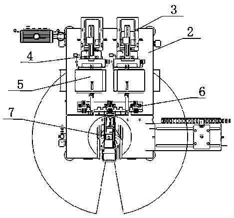
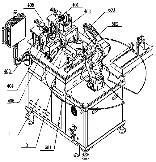
[0032] Such as Figure 1~5 As shown, a sheet feeder includes a base 1, a feeding unit and a six-axis robot 7, at least two groups of feeding units are provided on the base 1, and a mounting plate 2 is provided on the base 1, and the feeding unit is installed on On the mounting plate 2, each group of feeding units includes a carrying mechanism 3, a transport mechanism 4, a stripping mechanism 5 and a waste processing mechanism 6, and a six-axis robot 7 cooperates with the stripping mechanism 5;

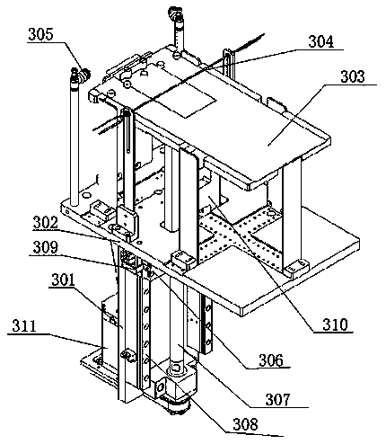
[0033] The carrying mechanism 3 includes a lifting module, a supporting plate 302, and a sheet material lifting plate 303. The lifting module is located on the lower end surface of the mounting plate 2, the supporting plate 302 is fixedly installed on the upper end of the mounting plate 2, and a sheet is arranged above the supporting plate 302. The material lifting plate 303, ...


PUM


Abstract

The invention discloses a sheet feeding machine. The sheet feeding machine comprises a base, feeding units and a six-axis robot, and is characterized in that the base is provided with at least two sets of feeding units; the base is provided with a mounting plate; the feeding units are mounted on the mounting plate; each feeding unit comprises a supporting mechanism, a conveying mechanism, a peeling mechanism and a waste disposal mechanism; and the six-axis robot is matched with the peeling mechanism. Through cooperation between the supporting mechanism, the conveying mechanism, the peeling mechanism, the waste disposal mechanism and the six-axis robot, sheet release paper is peeled, and products are transferred, the automation degree is high, the production efficiency is high, and the product production accuracy is ensured.

Description

technical field [0001] The invention relates to the technical field of sheet material feeders, in particular to a feeding device for processing and transferring sheet materials. Background technique [0002] The feeding process of the sheet material feeder includes the handling, stripping, conveying, and transfer of the sheet material. During the feeding process, semi-finished or finished components will be placed on the load-bearing workbench, waiting for the next step to peel off the bottom layer of the material, because the materials are stacked and pushed together, and the materials often need to be moved during the working process. At present, this kind of common load-bearing workbench generally has a table top, and a support base is set under the table top. The materials to be processed or products are placed on the table top, and there are certain limitations in the lifting height. At the same time, the mechanical arm transports the materials It is easy to absorb mul...

Claims


Application Information

Patent Timeline
Patent Type & Authority Applications(China)
IPC IPC(8): B65H1/14B65H3/08B65H3/48B32B38/10
CPCB65H1/14B65H3/48B65H3/0816B32B38/10
Inventor 陈建董明伟
Owner 禾准电子科技(昆山)有限公司
Learn More