
Drainage structure and construction method of a wooden arch ancient corridor bridge

A drainage structure and drainage pipe technology, which is applied in the direction of roof drainage, building structure, roof, etc., can solve the problems of rain shelter and rain prevention, low drainage efficiency of wooden arch ancient corridor bridges, low rainwater drainage efficiency, etc., and achieve reduction The effect of accumulating rainwater and promoting drainage

Active Publication Date: 2021-03-02
金华市广和古建筑技术研发有限公司
View PDF7 Cites 0 Cited by
  • Summary
  • Abstract
  • Description
  • Claims
  • Application Information

AI Technical Summary

Problems solved by technology

[0005] The purpose of the present invention is to address the many deficiencies of the prior art and provide a drainage structure and construction method for the ancient wooden arch bridge. Now, the rainwater is collected and recycled later by installing a device on the roof of the ancient bridge to facilitate drainage. Utilization not only increases the environmental protection ability, but also solves the low drainage efficiency of rainwater, and the rainwater spills into the interior of the corridor bridge, which affects the effect of sheltering from rain and rain. to the inside of the corridor bridge, thus affecting the use of the problem

Method used


Image

  • Drainage structure and construction method of a wooden arch ancient corridor bridge
  • Drainage structure and construction method of a wooden arch ancient corridor bridge
  • Drainage structure and construction method of a wooden arch ancient corridor bridge

Examples


Embodiment Construction

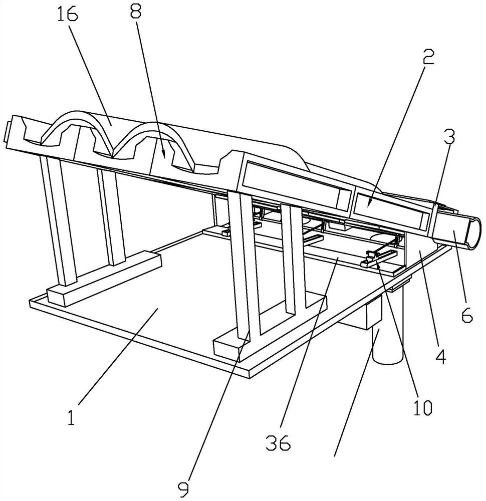
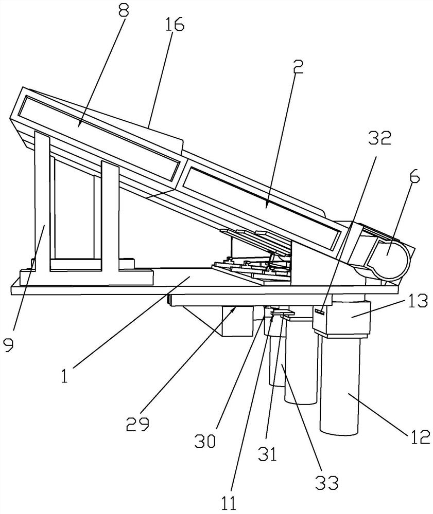
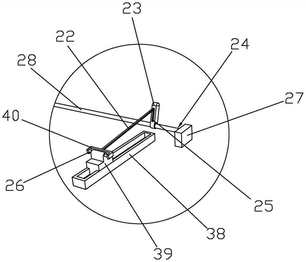
[0046]Such asFigure 1 to Figure 9As shown, the drainage structure of a wooden arched ancient gallery bridge of the present invention includes a support plate 1, on which a water guide block 3 and a waterproof plate 4 are arranged, and a water guide block 3 and a water guide block are installed on the waterproof plate 4 3 Tilt installation, the water guide block 3 has a hollow structure, the water guide block 3 is provided with a water guide groove 5, the water guide block 3 is provided with a water collection pipe 6 inside the water guide block 3, and the water collection pipe 6 is provided with a water inlet 7, a water inlet 7 and a water guide 5 Connected, the waterproof board 4 is provided with a first structure board 2, and the adjacent first structure boards 2 are plugged in. The support board 1 is provided with a support frame 9, and the support frame 9 is provided with a second structure board 8. The two structure boards 8 are connected to each other. The first structure boar...


PUM


Abstract

The invention discloses a drainage structure and a construction method of a wooden arch ancient gallery bridge, comprising a support plate, a water guide block and a waterproof plate are arranged on the support plate, the water guide block is installed on the waterproof plate, the water guide block is installed obliquely, and the water guide block is installed on the water guide plate. The water block is provided with a water guide groove, the inside of the water guide block is provided with a water collection pipe, the water collection pipe is provided with a water inlet, the waterproof board is provided with a first structural plate, the supporting plate is provided with a support frame, and the support frame is provided with a second structural plate , the support plate is provided with a sliding mechanism, the bottom of the support plate is provided with a connecting mechanism and a first drain pipe, the first drain pipe is provided with a connection box, and the connection mechanism is connected with the connection box. The construction method includes: 1) the basic structure of the wooden arch ancient corridor bridge; 2) the installation of the sliding mechanism; 3) the installation of the first construction plate and the second construction plate; 4) the installation of the waterproof structure; 5) the installation of the eaves. The invention solves the problem that the drainage efficiency of the existing wooden arch ancient corridor bridge is not high, and the rainwater is easily blown to the inside of the corridor bridge by strong wind, thus affecting the use.

Description

Technical field[0001]The invention specifically relates to a drainage structure of a wooden arch ancient gallery bridge and a construction method thereof.Background technique[0002]Covered bridges, also known as Hongqiao and Centipede Bridges, are roofed bridges that can protect the bridges, and at the same time provide shade and rain, for people to rest, communicate, and gather. There are mainly wooden arched gallery bridges, stone arched gallery bridges, Muping gallery bridges, wind and rain bridges, pavilion bridges and so on.[0003]The ancient architectural gallery bridges across the country have various forms and different styles. The structural characteristics of the bridges can be divided into four categories: wooden beam gallery bridges, stone beam gallery bridges, wooden arch gallery bridges and stone arch gallery bridges. The wooden beam structure gallery bridge can be divided into five types: wooden flat beam gallery bridge, wooden simple beam gallery bridge, wooden outrigg...

Claims


Application Information

Patent Timeline
Patent Type & Authority Patents(China)
IPC IPC(8): E04D13/04E04D13/08
CPCE04D13/0445E04D13/0481E04D13/08E04D2013/0486
Inventor 朱卫安陈飒明丁俊楠赵灿明姚建材刘应学
Owner 金华市广和古建筑技术研发有限公司
Learn More